BEAP
Prepared by:

HBA Architecture & Interior Design, Inc.
One Columbus Center, Suite 1000
Virginia Beach, Virginia 23462
757-490-9048
www.HBAonline.com

Vanasse Hangen Brustlin, Inc.
5544 Greenwich Road, Suite 302
Virginia Beach, Virginia 23462
757-490-0132
www.VHB.com
BEAP
Base Exterior Architectural Plan
This Base Exterior Architectural Plan (BEAP) is the official direction for designing, developing, and reviewing all Installation construction and renovation projects at Marine Corps Base (MCB) Camp Lejeune and Marine Corps Air Station (MCAS) New River.
Chapters 1, 2 and Appendix A: Summary of Field Work provides a comprehensive background in understanding the historical and existing Installation context. The design guidelines in Chapters 3 and 4 provide direction on how to make MCB Camp Lejeune and MCAS New River more attractive and functionally organized Installations, but also encourage creativity in architecture, planning, landscape architecture and site design.
The design guidelines summarize the overall recommended design styles and elements for the Installation, which has been subdivided into Special Districts. The basic process for using this document for a design project is as follows:
1. Consult the Special District Map, Section 2.3.1, to determine approximate project location.
2. Consult the design guidelines in Chapter 3 for more detailed design development information. The design guidelines include instructions on the following topics:
· Site planning: gates, roadways and access, building siting, parking, pedestrian circulation, plazas and courtyards, common areas/activity nodes/open spaces and parks, service areas, and maintenance and improvements (Common Operational Level or COLs)
· Landscape architecture: focal point devices, memorials and static displays, flagpoles, plant material, signage, paving services, bollards, fencing, and utilities.
3. Consult Chapter 4 for the design guidelines of the specific Special District or Sub-district in which the project is located. These guidelines will cover the following topics:
· Massing
· Windows and Entrances
· Body and Roof Materials
· Colors
· Details
· Precedent Buildings
4. Submit an Application for Certificate of Compliance during the Design Development Submittal or 35% Design Submittal. The Architectural Review Board will make an initial assessment of the project to ensure design direction is in compliance with the BEAP.
5. Submit an Application for Certificate of Compliance for the Pre-Final or 100% Design Submittal. The Architectural Review Board will make a final decision on approving the Certificate of Compliance.
This Base Exterior Architectural Plan (BEAP) is the official direction for designing, developing and reviewing all installation construction and renovation projects at MCB Camp Lejeune and MCAS New River.
This BEAP replaces the previous March 1997 version and has a two-fold purpose. It provides aesthetic and functional direction for new development and renovation efforts, and it helps to protect and preserve the Installation’s natural and historic resources. Though preservation of resources must be a high priority, the guidelines must be flexible enough to allow for renovation, expansion, or demolition of inadequate facilities that may need to be removed to make room for other mission essential facilities.
MCB Camp Lejeune is home to the II Marine Expeditionary Force (II MEF), the Marine Forces Special Operations Command, 2nd Marine Division, 2nd Marine Logistics Group, the Naval Hospital, and several other major subordinate commands. The mission of MCB Camp Lejeune is to maintain combat-ready units for expeditionary deployment.
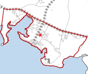
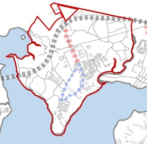
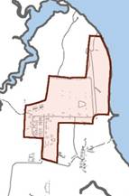
The study area includes developed land within the bounds of MCB Camp Lejeune and MCAS New River, as well as two remote locations: Oak Grove Outlying Landing Field and Morehead Port. See map below.

BEAP Study Area
1. Identify and strengthen the formal site planning elements at MCB Camp Lejeune and MCAS New River.
2. Improve wayfinding for Installation occupants, their customers and visitors by developing a hierarchy of roadways and pedestrian paths, and establishing visual wayfinding elements including signage systems.
3. Identify visual assets and liabilities on MCB Camp Lejeune and MCAS New River. Provide direction to maintain assets and change liabilities.
4. Recognize and analyze the unique visual districts within Installations’ boundaries to classify the built environment style and a harmonizing theme to strengthen each district.
5. Initiate a process to control the architectural style and direction for all planned and imminent construction.
6. Establish clear visual environment design guidance both in a general sense and specific to individual districts.
7. Establish a process by which the guidance in the plan is routinely and effectively administered and implemented within each new modification or project.
8. Develop guidelines that apply to all built environment elements including buildings, walls, fencing, landscaping, utilities and pavements related to personnel and vehicular movement.
9. Recommend materials and construction elements that can realistically be maintained by local resources.
This section defines the major perceptual environment components and the terminology used in analyzing those components at MCB Camp Lejeune and MCAS New River. They include Special Districts, architectural styles, entries, landmarks and reference points, significant views, activity nodes, circulation routes, and Installation edges.
Humans typically utilize a mental visual-spatial map that helps them navigate and interact with their environment. We rely heavily on the visual environment and tend to organize areas into perceptual units. To visually comprehend the complexities associated with a Marine Base, it is appropriate to subdivide the Installation into units or Special Districts. Special Districts are pre-existing neighborhoods of development which are part of the formal and informal spatial maps at Camp Lejeune.
There are 13 Special Districts, some of which also have sub-districts with unique characteristics.
· Hadnot Point
· Hospital Point
· French Creek
· Cogdels Creek
· Wallace Creek
· Courthouse Bay
· Paradise Point
· Onslow Beach
· Camp Geiger
· Marine Corps Air Station New River
· Stone Bay
· Camp Johnson
· Entry Gates
There are three common architectural styles on Camp Lejeune by which some, not all, buildings may be classified.
Georgian. A formal arrangement of classical details, including pediments, pilasters, or columns.
Colonial Revival. Fashioned after the Georgian style, commonly with broken pedements and somewhat less detailed classical ornament
Shingle Style. Uniform covering of unpainted shingles, porch coverings and small groups of windows.
Entries are those areas an individual passes through to go from one district to another. For the purposes of this study, entries are gates that lead from off base to on base or from one major district to another.
Landmarks are points on the Installation that can be used for cognitive reference. Generally, a landmark is a physical object such as a tower, building, monument, or natural feature so distinctive from its surroundings that it becomes easily recognizable and memorable. Major landmarks on MCB Camp Lejeune and MCAS New River include:
· Parade deck at Hadnot Point
· Round-abouts at MCB Camp Lejeune
· Marine Corps Exchange complex
· Officers’ Club at Paradise Point
· Flight line at MCAS New River
MCB Camp Lejeune and MCAS New River benefit from views along the banks of the New River where development gives the greatest access to the water. These occur along large expanses of the river's edge, such as at Paradise Point, as well as in sheltered inlets in Courthouse Bay. A multitude of uses exist along these views, such as bachelor housing, recreation, and parking.
Activity nodes are definable areas that support high concentrations of activity. They generally coincide with major facility landmarks or buildings that house important functions such as headquarters. They can also occur in areas where a high level of vehicular or pedestrian traffic converges and interacts within spaces between facilities. Nodes can occur outside facilities in plazas, entrances or other outdoor spaces. Recreation and commercial functions can also generate high levels of activity and are commonly indicated as nodes. Nodes are often where the convergence of two major circulation routes occur.
Circulation routes determine the basis for much of what a person sees, which includes all roads, walkways and unimproved paths. The primary circulation routes, the roadways, become a framework for the organization of the Installation. Circulation routes provide physical access to all areas of the Installation and are used for wayfinding purposes.
Edges consist of definable elements that separate unlike districts. These edges can be open spaces, streets, walls, fences, rows of trees, sides of buildings, water bodies or landforms. In this analysis, edges are primarily limited to the Installation edge and areas between major districts. An edge attains significant visual strength if it has long lateral visibility and is impenetrable to cross movement, such as the Installation boundary fencing. Conversely, penetrable edges usually serve to join two districts together.
An overall Installation architectural theme sets the framework for guidelines and standards. This theme integrates the goals for the built environment with the broader non-facility goals and objectives of the mission at MCB Camp Lejeune and MCAS New River. Existing settings, buildings and structures were analyzed to determine the factors to provide the framework for the overall theme. (See Appendix A: Summary of Field Work.) This analysis concluded:
· An overall predominant architectural style presently exists at MCB Camp Lejeune, but some districts do not represent this style as much as others.
· Predominant materials, color, and forms do exist at MCB Camp Lejeune, but are not always consistently applied.
· Architectural character and positive visual impressions can be found in many areas of Camp Lejeune and are examples of proper treatment of historical districts and integration of contemporary architecture.
In addition to architecture, other visual support or infrastructure elements have been evaluated. This analysis concluded:
· The major roadways
· The larger scale landscape elements (trees and other mature vegetation including natural areas)
· Streetscape and site elements
· Signage and graphics
· Currently existing lighting
Defining a design theme for the Installation is one of the functions of this Base Exterior Architectural Plan. Assigning prominence to specific areas enhances orientation and wayfinding by highlighting their distinctiveness and sense of place within an overall coherent physical arrangement that visually and cognitively unifies the Installation. Extensive field work has revealed that the elements that appear most frequently throughout MCB Camp Lejeune are:
1. Red to red-brown brick, modular size
2. Concrete or stone foundation base and window sills
3. White door and window trim, eaves, gutters and downpouts
4. Gray aphalt or standing seam metal roofing
5. Gable-on-hip roof
Using the common items listed above as a nucleus, and taking into account the existing elements from the previous section, the overall architecture theme is traditional early American design and can be implemented through guidelines and standards that recognize the dominant character. Because of the visual and/or spatial separation that exists between several of the districts, separate standards are appropriate under a Special District design approach. Though the standard may vary among districts, common harmonizing elements are intended to unify the entire Installation. At the same time, wayfinding, district delineation, and spatial clarity depend on uniqueness. The guidelines must accommodate and encourage variety and uniqueness while incorporating harmonizing elements.
It is appropriate that some areas be treated as districts, independently or collectively, by function, use, density, topography, orientation, and/or architectural character. The dominant positive characteristics of the district are intended to be repeated to further reinforce and strengthen the definition of the district. Districts with historical or near-historical significance are intended to be reinforced through preservation or retrofit methods that support the area character. This methodology is used throughout the design guidelines.
Those serving aboard and visiting the Installation invest emotional qualities in the environmental design. This means each person’s surroundings comprise of connotations, memories, experiences, feeling, hopes and dramas. This forms a collective image, or urban legibility, and is not only the basis of spatial orientation but the key to providing a stimulating and healthy environment.
Improvements to the overall visual organization and aesthetics of MCB Camp Lejeune and MCAS New River will not occur by simply writing a generalized set of guidelines. Likewise, changes to the visual environment will not be positive unless they are following a prescribed format and intended direction. Guidelines are the starting point, but the implementation of a review process that directs development must be part of the process to positively affect the base. This BEAP is intended to cover the first few steps in the process that will eventually help to improve the overall visual environment and to contribute to protecting the positive elements that are already present.
This BEAP is a working document that will function as a guide to physical development and urban legibility, while at the same time, is flexible enough to account for changing conditions, priorities and programs. The decision making process for physical development must address site planning and design issues, as well as the financial and functional requirements of physical design and development. Aesthetic improvements cannot be achieved on a site-by-site or problem-by-problem basis, but must be based on a master plan which is properly conceived to allow each problem to be resolved as part of a total concept.
This document is MCB Camp Lejeune and MCAS New River’s official direction on facility and site development. It shall be used in developing, designing, and reviewing all construction and renovation projects on the Installation. The guidelines are meant to be specific enough to provide direction on how to make both Installations more attractive and functionally organized, but they are also meant to encourage creativity in site design, planning, architecture, and landscape architecture. The guidelines do not cover all physical elements commonly addressed by facility development. They only cover those elements needed to produce a historically correct design theme, where appropriate, and coherent physical development of the Base.
Marine Corps Base Camp Lejeune is located in Onslow County within the coastal plains of North Carolina and sits adjacent to the City of Jacksonville. The New River runs north and south through the Base, separating MCB Camp Lejeune from MCAS New River and the Greater Sandy Run training area.
MCB Camp Lejeune serves approximately 150,000 active duty, dependent, retiree and civilian employees, which is a significant part of the Jacksonville and Onlsow County populations. Over 25 percent of the county is part of the Armed Forces.
MCB Camp Lejeune and MCAS New River are surrounded by predominantly rural agricultural lands, which diversify into higher density areas near the urban centers of Jacksonville, Swansboro and Topsail Beach.
MCB Camp Lejeune is home to the II Marine Expeditionary Force (II MEF). The major commands include:
· II Marine Expeditionary Force (II MEF)
· Marine Corps Special Operations Forces Command
· 2nd Marine Division
· 2nd Marine Logistics Group
· Naval Hospital Camp Lejeune
· 22nd, 24th, and 26th Marine Expeditionary Units
· Marine Corps Engineer School
· Joint Maritime Training Center
· School of Infantry – East
· Marine Corps Combat Service Support School
· Field Medical Training Battalion – East
· Wounded Warrior Battalion – East
The mission of MCB Camp Lejeune is to maintain combat-ready units for expeditionary deployment. Marine Corps Base owns all the real estate, hosts entry-level and career-level formal schools and provides support and training for tenant commands – II Marine Expeditionary Force conducts operational planning for Fleet Marine Force commands; 2nd Marine Division is the ground combat element of II MEF; 2nd Marine Logistics Group is the combat service support element of II MEF; and 2nd Marine Air Wing, headquartered at Cherry Point, North Carolina, is the air combat element of II MEF. Additionally, the naval hospital provides primary medical care to service members and their families stationed at Camp Lejeune and Marine Corps Air Station New River. Marine Corps Special Operations Forces Command is the Marine Corps force provider for the US Special Operations Command (USSOCOM).
Among many other support units, MCAS New River is home to two groups of the 2nd Marine Air Wing: Marine Aircraft Group 26 which consists of tiltrotor squadrons, and Marine Aircraft Group 29 which comprises both heavy and light/attack helicopters.
The study area includes developed land within the bounds of MCB Camp Lejeune and MCAS New River, as well as two remote locations.
MCB Camp Lejeune: The largest contiguous portion of MCB Camp Lejeune consists of approximately 56,000 acres and occupies the land immediately to the east of the New River. Commonly referred to as “main side”, this part of the study area contains the majority of the Special Districts, administration, personnel support, and family and bachelor housing facilities.
Stone Bay: Stone Bay District is 2,700 acres of range training areas, administration and support facilities, as well as encompassing the Marine Corps Forces Special Operations Command complex.
MCAS New River and Camp Geiger: Collectively this area consists of 4,507 acres, including land dedicated to the Marine Corps School of Infantry East and the subordinate units of the 2nd Marine Air Wing, flight line, aprons, and supporting areas.
Camp Johnson: An ancilliary camp located between MCAS New River and MCB Camp Lejeune. Camp Johnson is approximately 1,552 acres consisting of primarily military education facilities.
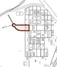
Oak Grove: An outlying landing field (OLF) to the north of MCB Camp Lejeune located outside of Pollocksville, North Carolina.
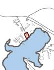
Morehead Port: Located in Morehead City, North Carolina, this area consists of a small cluster of buildings for use by the Marine Corps during port operations.
Camp Devil Dog: Approximately 134 acres of austere training facilities primarily used by the School of Infantry. Camp Devil Dog is located to the south of MCAS New River along Highway 17.
Greater Sandy Run: A vast manuever area of 41,227 acres, Sandy Run is on the western edge of the military reservation and represents the largest expanse of training area for the Marine Corps on the east coast.
This BEAP replaces the previous BEAP version (dated March 1997) and has a two-fold purpose. It provides aesthetic and functional direction for new development and renovation efforts, and it helps to protect and preserve the Installation’s natural and historic resources. Though preservation of resources must be a high priority, the guidelines must be flexible enough to allow for renovation, expansion or demolition of inadequate facilities that may need to be removed to make room for other mission essential facilities.
Major phases for the BEAP include:
· Identify the overall project goals
· Complete field work to determine assets, liabilities, dominant elements, perceptual districts and spatial structure
· Develop objectives for site planning, architecture, landscape architecture, signage and lighting
· Map perceptual districts and spatial structure
· Map assets and liabilities
· Map historic structures and districts
· Map road hierarchy and structure
· Develop specific guidelines
· Develop examples of what to do and not to do
· Describe acceptable building materials
· Develop a review process
· Obtain consensus and approval on the guidelines
· Produce a final document and brochure
Design guidelines are developed for the following:
· Site planning: gates, roadways and access, building siting, parking, pedestrian circulation, plazas and courtyards, common areas/activity nodes/open spaces and parks, service areas, and maintenance and improvements
· Architecture: building design, building entrances, building renovations and additions, historic architecture, and the Building Color Design Guide
· Landscape architecture: focal point devices, memorials and static displays, flagpoles, plant material, signage, paving services, bollards, fencing, and utilities.
1. Identify and strengthen the formal site planning elements at MCB Camp Lejeune and MCAS New River.
2. Identify and protect the Historic District’s significant resources. This BEAP will focus on the exterior visual environment where buildings form the edges of spaces as well as the site “grounds” within the Historic District.
3. Improve wayfinding for Installation occupants, their customers and visitors by developing a hierarchy of roadways and pedestrian paths, and establishing visual wayfinding elements including signage systems.
4. Identify visual assets and liabilities on MCB Camp Lejeune and MCAS New River. Provide direction to maintain assets and change liabilities.
5. Recognize and analyze the unique visual and historic districts within MCB Camp Lejeune and MCAS New River boundaries to classify the built environment style and a harmonizing theme to strengthen each district.
6. Initiate a process to control the architectural style and direction for all planned and imminent construction.
7. Establish clear visual environment design guidance both in a general sense and specific to individual districts.
8. Establish a process by which the guidance in the plan is routinely and effectively administered and implemented within each new modification or project.
9. Develop guidelines that apply to all built environment elements including buildings, walls, fencing, landscaping, utilities and pavements related to personnel and vehicular movement.
10. Recommend materials and construction elements that can realistically be maintained by local resources.
MCB Camp Lejeune is located in eastern North Carolina adjacent to the City of Jacksonville. The base consists of 14 miles of beach front along the Atlantic Ocean. The New River runs north/south through the base and Highway 24 separates MCB Camp Lejeune from Jacksonville. The Base serves approximately 150,000 active and retired military, their dependents, and civilian employees.
Originally Marine Barracks New River, established 1 May 1941, the Base’s first warehouse was a converted tobacco barn and the Base Headquarters a summer cottage. In December 1942, the Base was renamed MCB Camp Lejeune in honor of Lieutenant General John A. Lejeune ¾ 13th Commandant of the Marine Corps. Today, MCB Camp Lejeune and the adjacent New River Air Station are the largest concentration of Marines and Sailors in the world.
Camp Lejeune instituted its first BEAP in 1997. Because no formal documentation existed prior to that time, architecture and landscape evolved as a mixture of different forms, colors, materials, and styles. The first BEAP was designed to establish basic standards of appearance where none previously existed.
While the previous BEAP was successful at establishing color and material standards, it left other areas of building and landscape to the designer. When facility acquisition shifted to the Design-Build process, these areas became significant gaps in controlling aesthetics. Where the Design-Bid-Build process gave the Installations a large role in the design of a facility, Design-Build did not, and occassionally resulted in less desireable architecture and landscapes.
The primary difference in this BEAP is to address new methods of facility acquisition, incorporate newly developed areas of the Base, and provide more specific guidelines to control the physical appearances of the Installation.
This section defines the major perceptual environment components and the terminology used in analyzing those components at MCB Camp Lejeune and MCAS New River. They include Special Districts, architectural styles, entries, landmarks and reference points, significant views, activity nodes, circulation routes, and Installation edges.
The NAVFAC Installation Appearance Guide (IAG) uses functional district to analyze areas of an installation. Functional districts are areas unified by common functions, such as as administrative/ training, airfield, industrial, personnel support and waterfront. Instead of functional districts, MCB Camp Lejeune uses a system of distinct neighborhood areas, known as Special Districts. Special Districts are based on unique geographical areas, which, over time, have developed as separate districts as well as unique variations on the predominant architectural theme. Therefore, the BEAP uses Special Districts defined by elements such as architectural style, color schemes, and landscaping. The Special Districts this BEAP addresses are:
· Hadnot Point
· Hospital Point
· French Creek
· Cogdels Creek
· Wallace Creek
· Courthouse Bay
· Paradise Point
· Onslow Beach
· Camp Geiger
· Marine Corps Air Station New River
· Stone Bay
· Camp Johnson
· Entry Gates
· Greater Sandy Run
· Camp Devil Dog
These Special Districts contain sub-districts:
· Hadnot Point
− Industrial Sub-district
− Marine Corps Exchange
· Paradise Point
− Brewster Street
− Wounded Warrior Complex
· Stone Bay
− Historic Rifle Range
− MARSOC

Special Districts on MCB Camp Lejeune and MCAS New River
Architectural style is a way of classifying architecture largely by physical characteristics. Styles formed during certain architectural periods and were influenced by prominent designers, cultural context, climatic or economic conditions or a combination. These designs became so formalized that they constituted “style.”
Classifying architecture by style gives emphasis to characteristic features of design, irrespective of the historic period from which the style emerged. The identifying features of a style include a wide variety of elements that may or may not be found on a particular building. Some structures are often identified with only one or two primary stylistic elements or forms. But the majority of buildings are often simplified versions that attempt to mimic the basic ideas of these “high style” prototypes. And some are simply utilitarian structures designed purely to meet functional requirements.
Entries include both physical gateways into the installation as well as physical or implied gateways into Special Districts. Installation gateways functionally serve as check points for access, control, and security, as well as primary locations for informational and directional help to guide visitors to their destination. They also establish the initial impression of the Installation. Special Districts may have physical gateways or secondary security control points. Entries may be implied by signage, landscaping, change in color scheme or an architectural feature. Refer to Section 3.4.6 for signage.
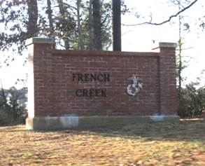
This sign on McHugh marks the gateway to French Creek
Landmarks are visual features that are distinctive and memorable. They serve as orientation of guiding devices because they help create a mental map of the Installation. MCB Camp Lejeune and MCAS New River have several primary landmarks:
· Parade deck at Hadnot Point
· Round-abouts at MCB Camp Lejeune
· Marine Corps Exchange complex
· Officers’ Club at Paradise Point
· Flight line at MCAS New River
Significant views provide a positive visual context. These include near distant views such as the Goettge Memorial Field House and the historic administration buildings along Holcomb Boulevard from across the main parade deck. Distant views include those along the New River from various vantage points on the Installation.
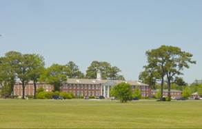
The main parade deck offers several near distant views
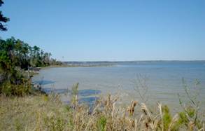
Example of a distant view along the bank of the New River
Activity nodes are generators and collectors of activity. Some nodes are highly defined with a specific physical enclosure, such as a courtyard or plaza, which heightens the user’s sense of functional purpose and detail. Others are defined by important land use, landmarks or spaces that are defined by their active functions. Nodes on the Installation include:
· Marine Corps Community Services
· Parade decks
· Base theaters
· Clubs and function halls

Activity nodes on MCB Camp Lejeune and MCAS New River
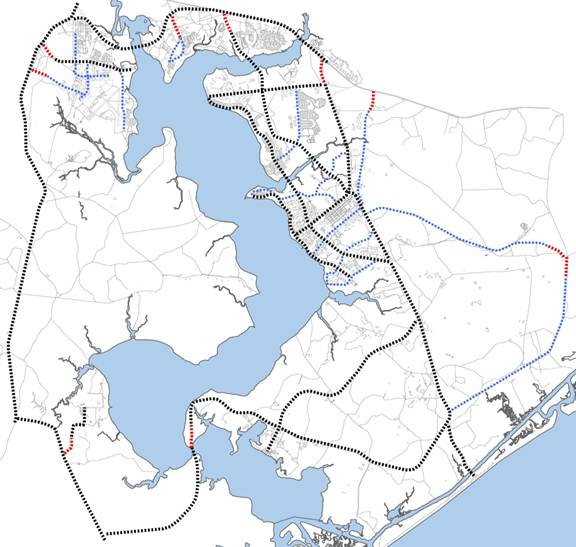
Primay vehicular circulation on MCB Camp Lejeune and MCAS New River

Circulation routes include vehicular circulation and pedestrian circulation. Our image of the environment is influenced most directly by the views from the roads. Movement along roads causes a succession of perceptions and experiences that are related in time and space. Good roads are not only safe and convenient, but orderly, articulate and visually distinguishable from others.
Vehicular routes may be classified by their level of traffic. Primary routes provide access to and from the gates as well as direct connection between major nodes. Secondary routes distribute traffic from the primary routes to activity nodes in each functional or physical district. Tertiary routes connect clusters of buildings and other traffic generators to the secondary routes.
Sidewalks and trails provide a similar experience for the pedestrian but with a greater emphasis on detail and textures. Sidewalks are often related to streets or buildings while trails tend to be more informal and for recreational in use.
The general public's primary impressions of the station are gained from the appearance of the edges. Improperly maintained, inadequate or inconsistent screening of negative visual areas will not present the installation in a proper manner. Likewise, district edges, when not properly planned, may have a negative impact on adjacent uses. When conflicting land uses adjoin (such as housing adjacent to industrial), care must be taken to screen negative visuals, sound, dust and light impacts from one use to the other.
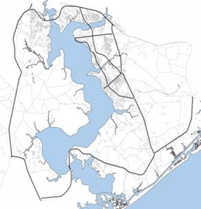
MCB Camp Lejeune and MCAS New River have a vast amount of natural environment in which Marine units conduct maneuver training. The Greater Sandy Run Area and Training Area West (Verona Loop) make up over half of the entire land mass of the combined Installations. These areas are relatively flat coastal plains crossed by shallow valleys and meandering stream channels. Vegetation consists of a mix of pines and hardwoods and large areas of scrubland and wetland vegetation. MCB Camp Lejeune contains areas of protected flora and fauna, including the endangered Red Cockaded Woodpecker. These areas should be identified prior to development planning by coordinating with the Installation and Environment staff.
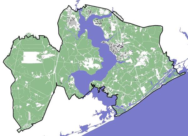
Green indicates vegetation while black and gray areas are developed. The Greater Sandy Run training area comprises most of the natural environment on Base.
MCB Camp Lejeune is bound by Highway 24 to the North, Highway 172 to the East, and the Atlantic Ocean to the South. Highway 17 bisects the western portion of the Base. Developed areas of the Base are located centrally along the New River while training functions are located in surrounding wooded areas. For the most part, mature stands of pines denote the outer boundaries of the base, extending a positive image.
MCB Camp Lejeune is divided into a network of Special Districts which are based on unique geographical locations. These Special Districts delineate the character of Camp Lejeune through distinct architectural style, color schemes, and landscaping.
Hadnot Point is located in the geographic center of MCB Camp Lejeune and is the architectural and landscape soul of the Installation.
Primary roads include Holcomb Boulevard and McHugh Boulevard, which traverse Hadnot Point along two perpendicular axes and are heavily used. Julian C. Smith Road (locally known as River Road) parallels McHugh Boulevard but its slower speeds and use as a running route make this a secondary road. Birch Road and Louis Road are also secondary roads, both serving four corners and outer reaches of Hadnot Point.
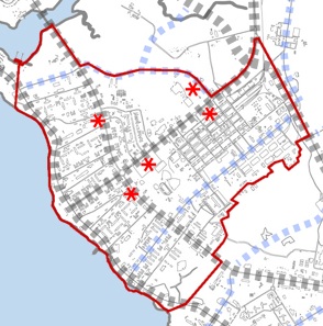

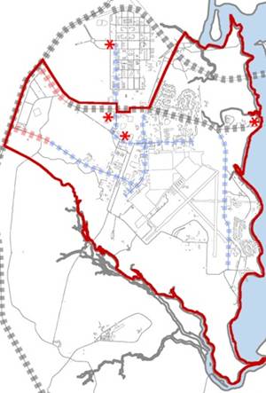
Hadnot Point
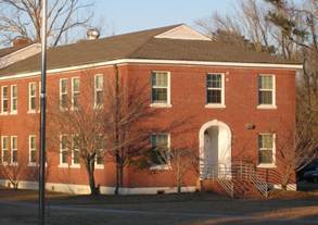
Hadnot Point contains an extensive Historic District which follows parts of Holcomb and McHugh Boulevards. The consistent Georgian architecture as well as the continued use for command services sets the character and importance of this area.
EXISTING ARCHITECTURE
A common palatte of colors and materials as well as classical elements of the Georgian style are ubiqutous. Combined these features evoke a sense of heirarchy and formality, as well as traditional values.
· Red to red-brown brick
· White base foundations, sill, and lintels
· White door and window trim
· Gray asphalt or standing seam metal roof
Building facades are largely symmetrical and entryways embellished. Other common details include:
· Cupolas
· Quions
· Raised concrete foundations
· Molded cornices
· Hipped or gable-on-hip roofs
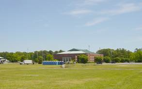
French Creek is located to the south of Hadnot Point and encompasses the land between French Creek and Sneads Ferry Road.
McHugh Boulevard is the primary route into this district, followed by secondary roads Julian C. Smith Road and Gonzales Boulevard. Sneads Ferry Road borders the east side of the district and is the primary means of getting to Cogdels Creek.
French Creek is the least cohesive district in terms of overall theme and architectural styles. Its sporadic development through the 1980s and 1990s resulted in a variety of materials, colors, and forms:
· Red to brown brick
· Stucco and metal panel
· Low slope, hipped, gable, or gable-on-hip roofs

French Creek
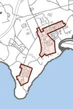
Courthouse Bay developed both as a training area as well as means of access to the New River and the Atlantic Ocean littoral. It is far removed from main side Camp Lejeune, located 2.5 miles south, toward the mouth of the New River as it meets intracoastal waters. This district is divided into two parts connected by a narrow strip of land.
NC Highway 172 bounds the north edge of Courthouse Bay, which has two primary entrances: Horn Road on the eastern side and Courthouse Road on the western side.
Courthouse Bay
This district is an artful mix of Georgian-like original structures and contemporary architecture. Materials and colors include:
· Brick, red and red-brown
· White, light gray foundations, sill, and lintels
· White door and window trim, eaves, gutters and downspouts
· Medium gray and dark gray asphalt or standing seam metal roofing
Common ornamental details:
· Cupolas
· Quions
· Raised concrete foundations
· Water table lines
· Molded cornices
· Monitor and clerestory windows
· Entryway canopies
· Distinctive water tables
· Brick mansonry details
Paradise Point, named after a peninsula of land that is formed by a bend in the New River, is comprised of single family housing, community, and other personnel support facilities.
Its primary circulation route is Seth Williams Road, an extension of McHugh Boulevard, which shadows the river’s edge and connects to Brewster Road by means of a roundabout. Stone Street completes the triangle that forms the district.
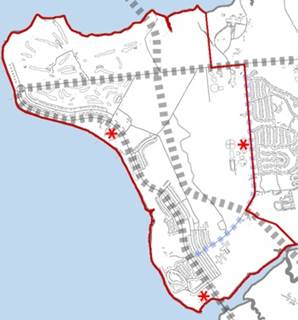
Paradise Point
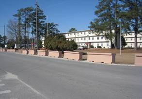
Although there are no historic districts in Paradise Point, there are ample examples of period architecture that make the character of this area clear and distinct. Georgian style buildings, interspersed between single family dwellings, echo the design elements of Hadnot Point. The Officers’ Club, surrounding BOQs, and Marston Pavillion suggest the time honored traditional values of the Marine Corps with the symmetry and rhythm of fenestration, basic solidity of brick masonry and class of white trim and moulding.
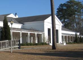
Marston Pavilion
Located adjacent to MCAS New River, Camp Geiger is one of the oldest parts of Camp Lejeune. Originally developed as an actual camp site, it was the temporary home of the first Marine units to be stationed in the area.

Camp Geiger
Camp Geiger is on the north edge of the air station boundary, cradled by the Jacksonville NC 17 Bypass to the north. Entrance is by way of the Air Station via Curtis Road. 'A' Street runs north south along the edge of a gridded street network.
After Camp Lejeune headquarters moved to Hadnot Point, Camp Geiger was left relatively unchanged from the 1950s until the 1970s. Today there is a variety of materials and detail, including:
· Red brick and concrete
· Hip, gable, and low slope roofs
· Gray or green asphalt shingles or light gray standing seam metal roofing
· White banding across the facades
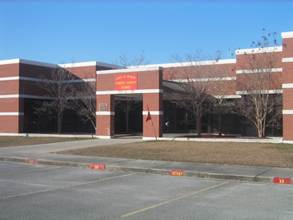
Academic facility with distinctive white banding
Marine Corps Air Station New River is relatively independent from MCB Camp Lejeune, although the two share many missions, training areas, and some services. For the purpose of this study, MCAS New River is included as a Special District.
MCAS New River
New River is located west of the river and has two entry gates, Curtis Road and Douglass Road, which serve as primary routes into the installation. Several secondary routes cross between, and provide circulation around the air field district.
The character of New River is contemporary and often utilitarian. Materials and colors consist of:
· Brick, concrete block, stucco and metal panel, typically beiges and white
· Low slope, gable or gable-on-hip roofs
· Green standing seam metal roofing
· Pilaster detail typical on two story structures
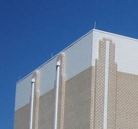
Pilaster detail on a high bay simulation facility
Stone Bay consists of marksmanship training facilities, a reserve training compound, and the US Marine Corps Forces Special Operations Command (MARSOC) complex.
This area is located across the New River from Hadnot Point and accessed via Highway 17. The main entrance, Range Road, skirts the MARSOC complex and terminates at the ranges.
Stone Bay
This district is divided into two distinct themes: a historic area after the Georgian style and the MARSOC complex, which has its own contemporary architectural language, loosely based on classical detail. The historic Rifle Range area consists of the following:
· Brick, red and red-brown
· White, light gray foundations, sill, and lintels
· White door and window trim, eaves, gutters and downspouts
· Gable-on-hip roofs
· Medium gray and dark gray asphalt or standing seam metal roofs
· Cupolas
· Raised concrete foundations
· Water table lines
· Molded cornices
Typical architecture in the historic district of Rifle Range
MARSOC consists of the following:
· Single course block foundations
· Recessed friezed detail at cornices
· Standing seam metal hip roofs
· Brick soldier coursing, reveals, and set backs
· Hip roofs

Typical MARSOC facility with brick detail and translucent wall panels
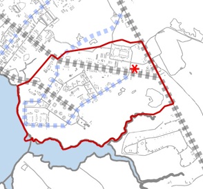
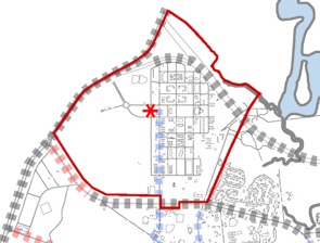
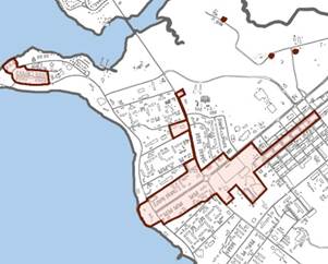
Camp Johnson is located between MCB Camp Lejeune and MCAS New River, and is bordered by the Jacksonville NC 17 Bypass to the north and waters of the New River on three sides.
Montford Road is the entrance to this district and continues south to a peninsula of land known as Montford Point.
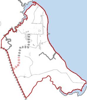
Camp Johnson and Montford Point
Camp Johnson experienced a significant time of little to no development after an initial surge in the 1940s. This gap is visible in the character of the historic buildings and the contemporary structures that began arriving in the 1980s. Elements of the historical district include:
· Beige or white facades, usually stucco
· Brick framed windows and doors
· Gray asphalt shingles
· Gable roofs and shed roofs above entries
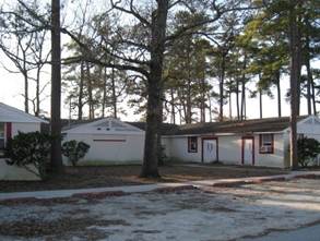
Much of Camp Johnson is single story buildings, shaded by tall pines and otherwise unimproved
Contemporary architecture is varied, but the predominant materials and colors include:
· Brick, various colors of reds and browns
· Two or three brick colors, split horizontally or vertically across the facade
· Standing seam metal roof of various colors
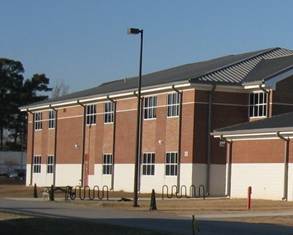
This academic facility uses three brick colors
Camp Lejeune Environmental Management Department has identified individual buildings and historic districts that are eligible for listing in the National Register of Historic Places, as of the year 2008. These are described in detail in a document available from Environmental Management:
Historical Architectural Evaluations, Marine Corps Base Camp Lejeune, Onslow County, North Carolina (Bowers, Dixon, and Jacobe 2008)
Historic districts are regarded as a cultural resource to be protected and preserved. The buildings and monuments not only reflect a high degree of design, workmanship, and materials, but possess a central importance in defining and maintaining the historic and architectural character of the Base. Designated historic districts on Camp Lejeune include the following:
Assault Amphibian Base (Courthouse Bay) and Camp Geiger Chapel and Entrance Circle
Command Services/Regimental Area No. 3 (Hadnot Point), Parachute Training, and Naval Hospital/Surgeon’s Row
Montford Point Camp No. 1, 2 and 2A and Stone Bay Rifle Range
Although the National Register considers all resources eligible for listing as equal, Camp Lejeune has categorized historic districts and buildings in order to prioritize preservation and guide repairs and other treatment.
The Environmental Management Department manages changes to historic districts and buildings. Guidelines are available in the following document:
Guidelines for Historic Buildings Management, Marine Corps Base, Camp Lejeune, Onlsow County, North Carolina (The Louis Berger Group, 2008)
There are three common architectural styles on Camp Lejeune by which some, not all, buildings may be classified. These are the following:
Georgian
The Georgian Style was formed from 1700 to 1800 and is characterized by a formal arrangement of classical details based on a symmetrical façade. Often the entry is emphasized by a pediment or monumental pilasters or columns. Common elements include water table line, pedimented dormers, and quions.

Building 15, Hadnot Point
Colonial Revival
Formed from 1870 to 1920, the Colonial Revival Style is a combination of Colonial and contemporary elements. Similar in formality to the Georgian style, Colonial Revival facades may exaggerate their individual ornamental elements. A common historical detail among these buildings is the broken pediment above the entryway.
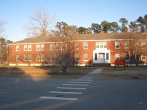
Walsh Hall, Rifle Range
Shingle Style
The Shingle Style dates between 1880 and 1900 and is characterized by a uniform covering of unpainted wood shingles, including roof and façade. Roof lines typically continue to create porch coverings. Windows are usually small and grouped in twos and threes.
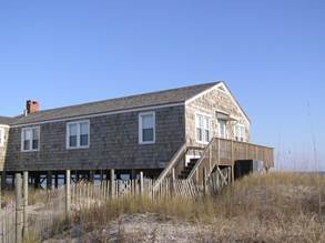
General Officers’ beach house, Onslow Beach, is in the Shingle Style
The visual setting and natural environment of the Carolina coastal plains is one the greatest assets of MCB Camp Lejeune and MCAS New River. The Installation invests in the recreation facilities at Onslow Beach and continues to take great care in preserving the shore.

Onslow Beach
Greater view access to the edges of the New River on MCB Camp Lejeune would further take advantage of this asset.
The historic districts, closely associated with the growth of the Marine Corps, are another asset which the Base should continue to take advantage of. These districts offer not only good examples of early American architectural styles, but a window into past significant events.
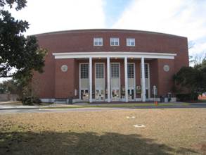
Base Theater at Hadnot Point
Water recreation opportunities at both MCB Camp Lejeune and MCAS New River are assets that the Installations have recognized and are using. Marinas provide access to the river waters and shoreline via piers, boat slips, and basic marina buildings. Investment in upgrading these facilities would further enhance the Installations' enjoyment of the New River.
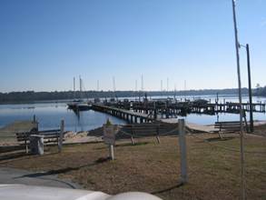
Marina at MCAS New River
The primary liabilities of MCB Camp Lejeune are a result of the core industrial functions of the Installation. Although efficiently located along the railroad and central to the cantonment, the Industrial Sub-district shares many of the same view scapes as the ceremonial center of MCB Camp Lejeune. This is not likely to change, but can be controlled through the preservation and renovation of the remaining perimeter surrounding the parade deck.
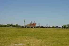
View of steam plant from across the parade deck
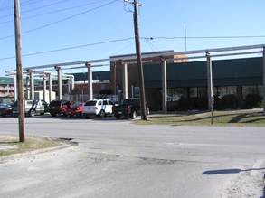
Vehicle barriers at MCAS New River are ubiquitous. Although placed for necessary protection or access control of key facilities, these barriers take away from the character of the district and become a memorable negative image of New River. Access control may be provided by other types of devices which have less visual impact, such as high curbs. If anti-ram passive barriers are required, decorative bollards may be installed around existing facilities without great impact on the Installation's architectural character.
Vehicle barriers are prevalent on MCAS New River
Similarly, above ground steam lines obscure building facades and become both a physical and visual barrier to the appearance of MCAS New River and parts of Courthouse Bay. When opportunities arise, steam lines may be routed below grade to free the visual and physical space which they currently occupy.
Elevated steam lines obscure building facades
An overall installation architectural theme sets the framework for guidelines and standards. This theme integrates the goals for the built environment with the broader non-facility goals and objectives of the missions at MCB Camp Lejeune and MCAS New River. Existing settings, buildings and structures were analyzed to determine the factors to provide the framework for the overall theme. (See Appendix A: Summary of Field Work.) This analysis concluded:
· An overall predominant architectural style presently exists at MCB Camp Lejeune, but is weakened by designs which dilute the formal rules of the style.
· Predominant materials, color, and forms do exist at MCB Camp Lejeune and MCAS New River in most districts, but some areas lack cohesion.
· Architectural character and positive visual impressions can be found in many areas of Camp Lejeune and are early American design styles.
In addition to architecture, other visual aspects of infrastructure elements have been evaluated. This analysis includes:
· The major roadways
· The larger scale landscape elements (trees and other mature vegetation including natural areas)
· Streetscape and site elements
· Signage and graphics
· Existing lighting
· Camp Lejeune environmental setting
3.1.1 DESIGN THEME FRAMEWORK
The architectural foundation of MCB Camp Lejeune and MCAS New River is based on a surge of construction during the 1940s when designers used Georgian and Colonial Revival styles for command, administrative, and support facilities across much of what is now mainside. Many of these structures are now in historic districts, as they are considered windows into the significant past of the military and the country. They also represent values found in the Marine Corps: solid fundamentals, tradition, order, and an affinity for the country’s roots. Therefore, the design theme for MCB Camp Lejeune and MCAS New River is based on early American design.
3.1.2 INTRODUCTION TO THE MECHANICS OF THE GUIDELINES
The purpose of these design guidelines is to establish standards for improving MCB Camp Lejeune and MCAS New River’s physical environment. The guidelines provide a framework for the enhancement of the visual setting of the installations through the siting, design, style and color of building and landscape elements for all improvements to the physical environment.
These guidelines are based on the BEAP goals and objectives, Section 1.7: Overall Project Objectives, and general operations and maintenance considerations. The design guidelines also refer to separate criteria specific to the MCB Camp Lejeune Historic District, and the remainder of the installation, when necessary.
Design guidelines have been developed for the following:
· Site planning: gates, roadways and access, building siting, parking, pedestrian circulation, plazas and courtyards, common areas/activity nodes/open spaces and parks, service areas, and maintenance and improvements (Common Operational Level or COLs -- See Appendix B)
· Architecture: building design, building entrances, building renovations and additions, historic architecture, and the Building Color Design Guide
· Landscape architecture: focal point devices, memorials and static displays, flagpoles, plant material, signage, paving services, bollards, fencing, utilities
Natural and cultural resources must be maintained, protected, and possibly enhanced. Every designer must be aware of the impact each new project will have on these resources and must design their project to complement or coordinate with the existing environment of the Installation. These resources give the Installations character and aesthetic appeal:
· Historic districts
· Waters edge along New River and tributaries
· Onslow Beach
· Monuments and statues
· Military equipment static displays
· Preservation areas
Incorporate antiterrorism and force protection (AT/FP) design with other design elements so that protection is attractive and unapparent. Elements that occur in site design which can unobtrusively protect the building and its inhabitants include:
· Drainage ditches and bio swales
· Ponds
· Open lawn and ground covers
· Lighting and mass notification systems
· Vehicle circulation
Other AT/FP devices can be incorporated into the site design without creating a fortress appearance:
· Berms and ditches
· Setbacks
· Fences and walls; seat walls
· Bollards and planters
Within the framework of the AT/FP planning standards, design all modifications and enhancements to existing facilities to be cohesive and compatible with the Installation's character.
Berms and Ditches
Berms and ditches offer an effective means of protection against vehicle-borne threats and have less visual impact than fences and other barriers. Soil berms on the protected side of ditches improve its effectiveness. Refer to UFC 4-022-02 Selection and Application of Vehicle Barriers for more information on ditches and berms.

Berms, when combined with ditches, can be integrated into site design and provide an effective vehicle barrier without detracting from the building design
Fences and Walls
Fences and walls provide both physical protection and a visual barrier to the building beyond. When an anti-ramming fence is required, use decorative black finished metal pickets to reduce the visual impact. Steel cable reinforcement should be integrated with the fence design such that it’s less visible.
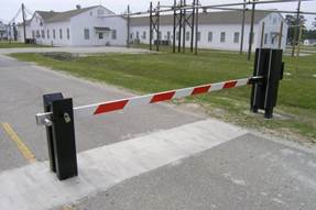
Crash-rated vehicle barrier across service driveway. If this type of barrier is required, it should be tied into a system of barriers which prevent by-pass.

The cable reinforcing in this fence design is hidden in the three rails and anchored to the ground through the post
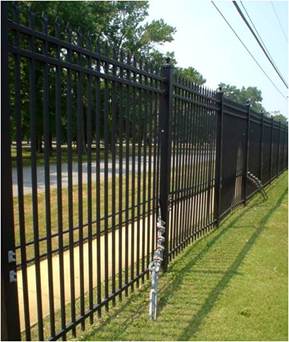
This fence design uses exposed cable reinforcing
Anti-ramming knee walls are an alternative to re-inforced fencing. Knee walls must have minimum dimensions and steel reinforcement to provide adequate protection, but may be veneered with the same materials as the building facade in order to blend into the design. Refer to UFC 4-022-02 Selection and Application of Vehicle Barriers for more information on anti-ram walls.

Knee walls, when properly constructed, serve as a vehicle barrier, but also provide the designer an opportunity to add visual interest to the site
Bollards and planters
Bollards and planters provide protection from vehicles while still allowing pedestrian traffic to move through. They must be constructed to specific construction standards as well as match the character of the Special District. Planters may be veneered in the same way as knee walls. Bollards designed for anti-ramming are substantial structures, constructed from structural steel pipe, and filled with concrete.
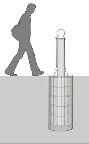
Anti-ram bollard indicating the structure required below grade; bollards shall have a decorative exterior
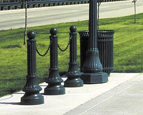
The character of these decorative bollards is appropriate for most districts
Sustainable planning and design is the practice of implementing strategies for buildings and landscapes that protect the environment, reduce life cycle costs, and improve the quality of living conditions. All of these strategies are compatible with improving the appearance of the Installations. Protection of the environment includes the use of recycled and environmentally friendly materials, managing stormwater through the strategy of low impact development, and limiting the impact of atmospheric emissions.
The reduction and conservation of energy is particularly important to the Marine Corps. Lower the costs of operation by reducing the use of energy through high performance building systems, employing renewable energy sources, optimizing solar orientation, and reducing the amount of materials and man hours required for maintenance. Optimize living conditions by providing good ventilation, natural task lighting, and avoiding items that emit chemicals.
LEADERSHIP IN ENERGY AND ENVIRONMENTAL DESIGN
The U.S. Green Building Council (USGBC) developed the LEED® (Leadership in Energy and Environmental Design) rating system to objectively judge a building’s sustainability. Categories by which buildings are rated include:
· Site sustainability
· Water efficiency
· Energy and atmosphere
· Materials and resources
· Indoor environmental quality
· Sustainable design innovation
Refer to the LEED® guidelines and other resources located on the Whole Building Design Guide (WBDG) website (www.wbdg.org/design/sustainable.php).
In addition to the sustainable site category, many LEED® credits affect the outward appearance of the building and impact the character of the Installation. Sustainable elements of a building should contribute positively to the aesthetic appeal. The next sections clarify these specific details.
LOW IMPACT DESIGN
The goals of LID are to create a developed site that closely maintains the natural hydrologic functions and conserves the maximum amount of the existing natural resources. The key elements of LID are custom site design, conservation, localized stormwater management, pollution prevention and hydrologic recharge of the local aquifer and/or adjacent wetlands. LID implies reduced reliance upon stormwater features such as catch basins, underground piping and concrete curbs, in favor of more natural features such as swales and infiltration basins. All of these elements work hand in hand to create an LID site design. See Section 3.2.12 Stormwater management and Low impact development.
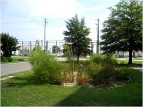
Biomass filtration basin at MCAS New River
DAYLIGHTING
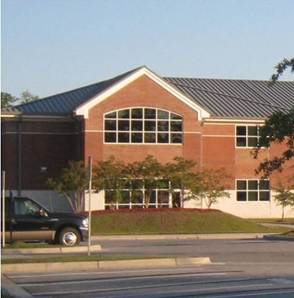
Daylighting design uses the sun to supplement or replace artificial lighting in interior spaces, even deep within the building. Daylight harvesting reduces energy costs and improves the quality of the work environment. Often this is done with a combination of strategies including large window openings, shading devices, unique building geometries, or glazing located high in a wall or roof. The key to using these strategies at MCB Camp Lejeune and MCAS New River is to incorporate them in the building without compromising the overall design concept and detracting from the district character.
The following are good examples of daylight design:
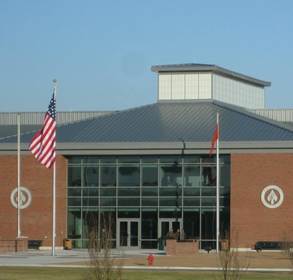
Roof monitor with translucent wall panels allows daylight into the atrium of the MARSOC Headquarters.
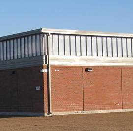
Wall panels are integrated into this façade without detracting from its overall appearance.
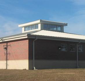
Roof monitor allows daylight to entry deep interior spaces in the Courthouse Bay fitness center.
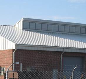
This maintenance facility in French Creek uses a clerestory window strategy to daylight vehicle bay space.
Window size and location should be the first strategy employed for day light harvesting. Position window openings above 2'-6" from the finished floor to maximize available light. Window glazing above 7'-6" is the most effective in allowing light deep into interior spaces. Thus, a window opening from 2'-6" to the height of the ceiling will collect the most light for a space. This results in tall window openings on the facade.
This window height spans from 2'-8" to 10'-0" to maximize sun light collection
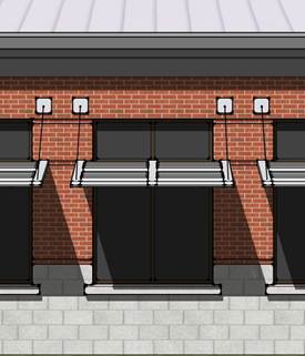
Exterior shading devices may be necessary to reduce the glare from direct sun light on working surfaces while still allowing light to enter the space. These devices greatly affect the building appearance and therefore must be fitting for the Special District, especially if that district uses historical context as a basis for style. While many shading device manufacturers offer modern-looking products, a more traditional look is achievable by designing from off-the-shelf kit of parts using outriggers, fins, and fascia pieces (below).
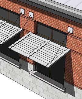
These sun shading devices emulate window shutters, a common element of early American architecture, and are congruent with many Special Districts
PHOTOVOLTAICS AND SOLAR HEATING
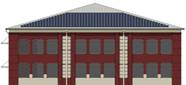
Photovoltaics and solar heating use large expanses of panels to collect the Sun’s energy to covert to electrical power or hot water. The decision to use a stand-alone structure or integrate panels with the building (for example, building integrated photovoltaics or BIPV) depends on many factors, but both have an impact on outward appearances. Low slope roofs provide an ideal location for these devices, are usually not visible from the ground, and have been installed on several buildings in the Industrial Sub-district of Hadnot Point. When incorporated onto high sloping roofs or as a stand-alone structure, renewable energy collection devices have a greater impact on the visual character of the district. Arrange panels in such a way that they are logically organized in harmony with the building and district's aesthetics.
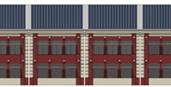
The BIPVs on these roofs are organized harmoniously with the building design
Photovoltaics arranged as parking shelter perform multiple functions besides energy collection. These structures have a large visual impact on a site, and shall be designed to enhance the style of the building and district.

This stand-alone photovoltaic structure is consistent with the early American design theme of Hadnot Point
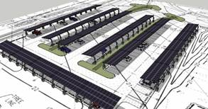
Photovoltaic array arranged to provide parking shade
RAIN WATER COLLECTION DEVICES
Cisterns are large water storage tanks used for rain water collection to be used for a building or site's non-potable water needs, such as flushing fixtures or irrigation. Rain water cisterns may be placed underground, but if not, they are likely to detract from the character of the building and district. Therefore, all above-ground cisterns must be properly screened so they blend in with surrounding architecture. Screen wall must use like-materials as adjacent structures and must comply with anti-terrorism/force protection standards.
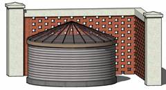
This above ground cistern is obscured from view with a traditional brick screen wall pattern that would be appropriate for most districts
Objectives:
Establish a hierarchy of welcoming entry Gates consistent with Base security requirements that enhance the identity and image of the MCB, provide visual distinction from the roadway streetscape.
Enhance security functions and clarity of vehicular movement, through well organized site layout and treatment of security shelters, circulation, controlled sight lines, signage and effective site lighting.
Design Guidelines:
Comply with UFC 4-022-01 Security Engineering: Entry Control Facilities/Access Control Points and UFC 4-010-01 DoD Minimum Antiterrorism Standards for Buildings.
MCB Camp Lejeune entrances shall express a clear hierarchy in their scale and appearance based on prominence and vehicle volume.
· Primary entry is given greater prominence through more substantial scale of roadway, special pavement, perimeter wall and fence detailing, massing of plant materials, lighting, and identity signage.
· Secondary entries maintain the elements and character of the primary entry, but at a reduced scale and extent of detailed treatment.
· Tertiary Entries to residential family housing areas should also be visually distinct from the adjacent roadside, with reduced number and scale of entry elements.
· Closed entrances should be clearly designated as such from Highway 24 and conflicting signage removed.
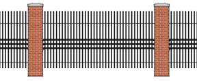
Entry fencing should be ornamental steel pickets (black) set on low brick faced wall (primary entry) and on concrete curb or mow strip at secondary and tertiary entries for ease of maintenance and consistency of design between entries.
Monument signage should be prominent at entry, without conflicting regulatory or directional signage detracting from integrity or full visibility of the identity sign either along the approaching roadside or within the entry setting. Directional and regulatory signage should be minimized to provide clarity of direction without extraneous clutter and conflicting visual cues.
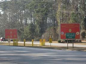
Signage at MCB Camp Lejeune Main Gate
Special paving treatments should be considered at entry gates both upon exiting from the local roadway and at sentry plaza to increase visual demarcation of entry and establish the importance of entry. By varying the extent of special paving the hierarchy of entries and circulation ways are reinforced. All entry gate roadways shall have well defined curbed edges.
Planting should enhance the dignity of the entry and should be composed of mass planting in scale with the overall space. Existing wooded edges work well to frame the entry space and should be augmented with seasonally interesting understory tree plantings to distinguish entries from typical perimeter edges. Clarity of space is paramount; planting should not be fussy or distracting from operation of entries. Planting should not obscure traffic or pedestrian sightlines at intersections or where surveillance is required.
Roadway, monument signage and architectural lighting at sentry house should reinforce circulation patterns, define edges of entry space, highlight attention to sentry house, and provide adequate lighting for security functions.
Provide security guard shelters, cover and lighting for inspection area per ATFP standards. Security cameras shall be mounted on light poles or building structure to reduce numbers of poles.
Objectives:
Establish a visually unified and distinctive perimeter of naturalized landscape edge along the public right of way that conveys a positive image of the Base to the surrounding community and instills pride in the Base community.
Preserve the wooded setting boundary buffer between public lands and military base facilities.
Design Guidelines:
Preserve, maintain, and enhance the mature tree stands at the camp perimeter. Remove diseased and dying materials. Clear deadwood and fallen branches from the outer most 25 feet of wooded edge.
Enhance and diversify existing stands by establishing perimeter planting program including planting of shade tree saplings and understory trees.
Prohibit development within the wooded perimeter buffer.
Establish consistent perimeter roadway treatment including street tree planting, roadway lighting, pedestrian walks, and security fencing
Provide a hierarchy of perimeter fencing (see 3.4.9 Walls and Fences) Maintain open ground plane to fencing and vertical clear zone to 20 feet for horizontal distance of 20 feet on the exterior side of fencing, 10 feet on interior side of fencing. Shrub masses shall be set back 60 from perimeter fence either side to maintain visibility by security patrols.
Objectives:
Establish a coherent framework of streets and walks that collectively contribute to a positive, unified Base community setting with a coordinated system of pavements, edging, lighting, signage, furnishings and planting.
Provide clear and safe, convenient circulation for motorists, bicyclists, and pedestrians.
Renew emphasis on visually reducing the scale of the roadways and encouraging pedestrian and bicycle circulation. Roadway cross section design shall give equal consideration to motorists, bicyclists and pedestrians in providing safe travel ways for all functions.
Design Guidelines
Conform to UFC 3-210-02 Design POV Site Circulation and Parking.
Promote expanded use of roundabouts on Base. Roundabouts express a distinct Base identity and improve traffic flow and intersection safety. Additionally, use of roundabouts reduces long-term operational costs associated with maintaining signalization and related structures and signage. Where employed, roundabouts should be carefully constructed with appropriate lane markings and traffic signs to clarify the intended movement patterns.
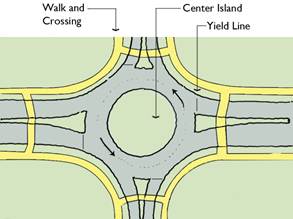
Promote expanded use of roundabouts
Priority consideration should be given to replacing signalized intersections at ceremonial locations and roadway focal points and to poorly performing interactions. Smaller scaled roundabouts should be considered for secondary and tertiary road intersections as a means of improving the overall aesthetic of the area and emphasis on non-motorized environment.
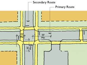
Intersection setbacks
Maintain sight lines and pedestrian crosswalks at intersections. Locate driveways and curb cuts a minimum of 50 feet from the intersection. Provide setbacks between roadway edges and building or parking areas at 30 foot (minimum) on primary roadways and 25 foot (minimum) on secondary roadways.
On street parking will not be permitted on primary or secondary roadways. On street parking will not be permitted on tertiary roadways without review and approval of the BEAP Review Board. In the event the Review Board approves on-street parking for a specific tertiary roadway setting, the following guidelines shall be met: on-street parking will be limited to parallel parking, one side of the road only, applying set back of 30 feet from the corner or 15 feet from the edge of any crosswalk, whichever is greater.
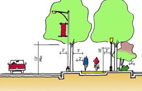
Recommended clearances at streetscape
Signs, hydrants, poles, headwalls, fences, and similar obstructions should be set back from the edge of road and walk/bicycle ways a minimum of two feet.
As street and pathway trees mature, branches extending over roadway shall be limbed up 12 feet (minimum) and at walks/bicycle ways 10 feet (minimum) from paved travel surface.
3.2.3.1 PRIMARY ROADWAY
Primary roadways include: Highway 24 (four lane divided highway), Highway 172, and Highway 17, Holcomb Boulevard, Main Service Road (McHugh and Seth Williams Boulevard), Brewster Avenue and Sneads Ferry Road.
Primary Roadways
New primary roadways greater than two travel lanes each direction are discouraged.
On street parking is prohibited.
Bicycle travel within the curb line is discouraged and shall be accommodated through off-road multi-use or dedicated bicycle ways.
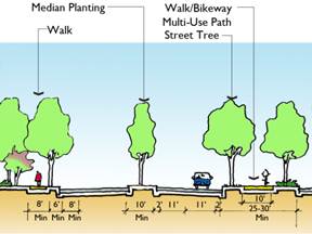
Primary Roadway Section
Primary roadways shall include pedestrian travel way (six foot width minimum) on either side of road. Multiuse pathways (minimum 10 feet width) should be considered in lieu of separate pedestrian and off road bicycle travel ways.
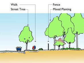
Street edges shall include a deciduous tree planting strip (six foot width minimum, eight feet or more preferred) at the curb edge. Deciduous shade trees reduce the perceived scale of roadway, slow traffic and create a more welcoming environment for pedestrians through separation from traffic and introduction of shade. Primary road street trees shall be formally aligned with the street and spaced at 40 to 50 feet on center typically, but may be closer in heavily trafficked pedestrian areas as part of a larger landscape plan. Mixed, informal grouping of trees and shrubs shall be provided at the rear side of the walk (eight foot minimum width) either to screen adjacent parking or as part of a larger “greenbelt” planting. Roadway medians ten foot width or greater shall be planted with ornamental and/or columnar tree plantings.
Street lighting should contribute to streetscape character, hierarchy and consistency in pole/fixture and quality of lighting. Consider using a combined approach of taller street and lower pedestrian level lighting or dual fixture lighting on shared poles in higher density pedestrian/commercial zones.
Primary roadways shall have reinforced/turfed shoulders and, only where absolutely required for stormwater management, vertical curbed edges/concrete curb and gutter edge.
Roadway signage and billboards shall be limited to reduce visual clutter and establish clarity for safe movement and improved way finding.
3.2.3.2 SECONDARY ROADWAY
Provide one (11 foot width) or two (22 foot width) travel lanes in each direction. If there is no bicycle lane within the curb line, consideration should be given to providing an additional one foot shoulder at each curb edge.
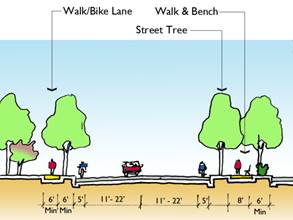
Secondary Roadway Section
On street parking is prohibited.
Third, center turning lanes should be considered for secondary roadways that include several vehicle entrances for safe maneuver of left turns. Turning radii should consider movement of large tactical vehicles, especially at operational areas.
Bicycle travel may be accommodated within the curb line through dedicated bicycle lane (five foot width) adjacent to the curb edge or through separate off-road multi-use (10 foot width) or dedicated bicycle ways.
Provide tree planting strip at the street edge, walks, and mixed planting landscape edge at rear of walk and lighting as in primary roadway section.
3.2.3.3 TERTIARY ROADWAY
Provide one travel lane each direction.
Alternatively, pedestrian and bicycle travel may be accommodated through a combined multi-use pathway. Roadways shall be edged with tree planting strip (six foot width minimum) and planted with shade trees spaced 40 feet on center (maximum). Adjacent landscape –either to rear of walk or contiguous to street tree planting - shall be composed of mixed stands of shade and understory trees as part of “greenbelt” planting.
Lighting shall be provided for combined roadway and pedestrian functions in character and scale with reduced roadway width.
On street parking will not be permitted on tertiary roadways without review and approval of the Architectural Review Board. In the event the Review Board approves on-street parking for a specific tertiary roadway setting, the following guidelines shall be met: on-street parking will be limited to parallel parking, one side of the road only, applying set back of 30 feet from the corner or 15 feet from the edge of any crosswalk, whichever is greater. Parking “bump outs” are encouraged to minimize road width at intersections, reduce extent of impervious pavement and improve pedestrian and vehicle safety.
Bicycle travel shall be accommodated within the roadway in “shared” vehicular/bicycle travel lane or through off-road pathways.
Pedestrian walkways (six foot width) shall be provided on at least one side of roadway.
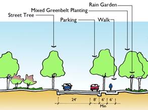
Tertiary Roadway Section
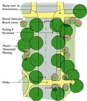
Tertiary Roadway Plan Diagram
3.2.3.4 SERVICE ROADWAY
Provide service roadways and driveways from secondary or tertiary roadways to adjacent parking areas or building service zones as required and allowed by ATFP requirements.
Maximum pavement width shall be 18 feet on typical access routes with intermittent use. Access road layout and related loading dock and service functions shall be designed for efficient movement and to minimize extent of impervious paved surfaces.
Align service drives to minimize service/ pedestrian crossings and visibility of service functions from public areas. Provide screening from public areas through planting or architectural quality screen walls.
Objectives:
Site buildings in positive physical and functional relationship to each other and surrounding site developments, circulation systems and open space to strengthen community identity and activity.
Establish clarity in site design, with logical order and sequence of spaces from site arrival to building entry.
Respond to the natural environment by limiting the extent of development-related disturbance, and preserving and enhancing the natural setting.
Reduce development related storm water runoff and enhance the stability of natural environment. Increase shade and reduce the need for infrastructure through wise siting and design of buildings and treatment of surroundings including implementation of extensive tree planting program.
Design Guidelines
Increase emphasis on creation of buildings segregated fro parking and site-focused design in response to ATFP requirements, with parking and roadways to the periphery and contiguous pedestrian/ bicycle open spaces and building environments at the core of community settings. Conform to UFC 4-010-01 DoD Minimum Antiterrorism Standards for Buildings.
Group built facilities in positive relationship to each other and adjacent exterior space within contiguous standoff zones to maximize site land use options and preserve the greatest amount of continuous impervious land.
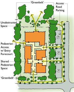
Siting Diagram
Orient building entries onto shared space and connect entries to each other by convenient pedestrian ways. Siting buildings to open onto pedestrian dominated open spaces is encouraged.
Present inviting and favorable articulated building facades toward adjacent streets and parking, even if not providing an entry at that face due to ATFP requirements. Avoid “fortress-like” appearances or otherwise minimally animated exterior facades.
Establish visible “entry forecourts” to provide welcoming exterior arrival spaces that lead one from off site to building entries.
Provide pedestrian and bicycle connections between buildings, to adjacent parking areas and to local roadway, pedestrian, and bicycle systems. Minimize conflicts between vehicular and non-vehicular circulation by providing separation and clarity in routes.
Provide convenient service, delivery and emergency access that is visually screened from public areas.
Site buildings in proximal relationship to other facilities to maximize efficiency of shared resources including walks, lighting, utilities and infrastructure, common facilities, roadways, parking, and long term care and maintenance of grounds.
Site buildings for maximum solar orientation benefit, daylighting opportunity, and reduced heating and cooling demand.
When determining location of development, protect existing natural resources. Avoid development within 50 feet of a water body, five feet of floodplain, and 100 feet from wetland edge.
When planning facilities, give consideration to future expansion of buildings, parking and stormwater management features.
Objectives:
Provide attractive, well organized, safe parking areas.
Reduce the overall need for surface parking area through efficient design and decreased use of vehicles on Base.
Reduce the environmental impact of parking and related amenities such as lighting.
Design Guidelines
All parking areas shall conform to UFC 3-210-02 Design: POV Site Circulation and Parking guidelines. Standard off-street parking layouts, curbing and striping shall be applied Base-wide. Restripe non-conforming areas, and areas with inefficient layouts or unclear circulation to gain stall count and/or reduce lot size. Remove unneeded pavement and create planting beds where removal of “painted islands” allow.
Prohibit on-street parking on all primary and secondary roadways. On-street parking on tertiary roadways will not be permitted without review and approval of the BEAP Review Board. In the event the Review Board approves on-street parking for a specific tertiary roadway setting, the following guidelines shall be met: on–street parking shall be limited to parallel parking, one side of the road only, applying set back of 30 feet from corner or 15 feet from edge of crosswalks, whichever is greater. Maintain fire lanes and safe pedestrian crossings.
Maximize parking efficiency and clarity of movement. Utilize standard 90 degree parking layout with two way access aisles.
Where possible, consolidate parking for multiple facilities so that buildings may be sited in clusters without separation by individual parking areas that may result in increased standoff zones.
Reduce visual impact of parking from roadways and adjacent use areas by establishing planting strips (eight foot width minimum) of informal planting of varied heights – shrub, ornamental trees and shade trees. Situate planting islands within the parking area to maximize screening potential and overall shade coverage.
Plant trees to shade parking areas. Provide 15 percent minimum shade coverage measured 10 years after installation of trees. Within the parking limits, provide pervious planting bed equal to or greater than five percent of the total square footage of paving area.
Provide defined curbed edge to all parking perimeters and planting islands. Curbed edge may include regular breaks or notched inlets as part of stormwater management design. If curb is not provided due to stormwater management design requirements, provide pre-cast parking bumpers at all parking stalls and provide edge of pavement line markings to discourage travel at the edge of pavement.
Provide two foot clearance at back of curb (bumper edge) for safety and ease of maintenance. Bollards, signage and other vertical objects shall be placed outside this two foot zone. Plant materials within this area should be 6 inch height maximum.
Opportunities to reduce stormwater management infrastructure demands through Low Impact Design features, including bio swales, infiltration basins and pervious pavement, shall be considered. Pervious pavement shall not be used in tactical vehicle paving areas or along delivery or trash pick-up routes within POV parking lots.
In order to limit the spread of light to adjacent facilities and restrict upward light spill, all parking area lighting fixtures shall be full-cutoff type. The use of LED lighting fixtures is encouraged.
Provide universal accessible parking spaces and associated pedestrian walks to facilities as required by State and Federal ADA regulation.
Provide designated motorcycle parking spaces 4 ½ feet wide by 12 feet long where need is demonstrated.
3.2.5.2 PARKING GARAGES
Objectives:
Provide attractive, efficient structured parking where demand justifies.
Reduce the visual impact of structures on adjacent buildings and outdoor use areas through effective siting, design and landscape treatment of adjacent standoff zone.
Reduce the overall demand for surface parking and related impacts including greater land disturbance, increased impervious surface, and heat island effect.
Design Guidelines
Establish “greenbelt” treatment in standoff zone between parking structure and unobstructed space of adjacent facilities. Greenbelt planting shall include mixed tree planting of understory and deciduous shade and/ or evergreen trees.
Consider approaches to grading that reduce the visual impact of structured parking through combining berming and naturalized planting.
Include pedestrian walkways linking structured parking to adjacent facilities, roadway and existing walk system in the implementation of new parking structures. Include bicycle parking and shower facilities within structured parking facilities and connections to the bicycle route system.
Parking garages shall be designed with the same style and characteristics as the Special District or sub-district in which they are built. This is particularly important because parking garages will be large, dominant structures on any site and its character will over-power other small adjacent structures.
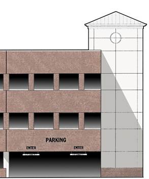
Above illustration shows a three story parking deck appropriate for Hadnot Point, Wallace Creek, or other Special District where the Georgian or Colonial Revival style is called for. The pre-cast stair or elevator tower is used to break up the expanse of the structure.
The exterior of parking garages shall be level and not express inclined ramps on the façade, in order to blend the structure's appearance with surrounding buildings.
Objectives:
Bicycle transportation provides an alternative to vehicular use on Base and results in reduced demand for roadway, parking and utility infrastructure.
Provision of safe, enjoyable bicycle travel ways encourages bicycle use for transportation and recreation.
Design Guidelines
Multi-use trails (10 foot width) for use by pedestrians and bicyclists shall be included within all primary streetscape sections. Primary roadway related multi –use trails may run parallel to roadways or more informally with curving alignments. Alignment design should respect nature of safe travel for both pedestrians and bicyclists.
Multi-use trails reintroduce bicycles to traffic at roadway intersections. Intersection and crosswalks design shall consider safety of all users.
Continued implementation of Base-wide multi-use trail and “Greenway” system serving bicyclists, joggers, and pedestrians and linking roadway system, areas of development, and natural areas is encouraged. The Greenway Master Plan allows planned incremental development. All Base projects shall include both pedestrian and bicycle connections to adjacent roadways and facilities.
Within secondary roadway sections, bicycle travel shall be accommodated within the roadway in dedicated bicycle travel lane (five foot width) or through adjacent off-road multi-use trail if one exists as part of overall trail system. On tertiary roads, bicycles “share” the vehicular travel lane.
All bicycle ways, whether dedicated bicycle trail, multi-use trail or bicycle roadway lane, shall have minimum two foot clear zone to either side of the travel way without vertical obstruction or abrupt grade drop.
As trees adjacent to bikeways mature, branches extending over travel way shall be limbed up 10 feet (minimum) from travel surface.
Multi-use trails and dedicated bike lanes intended for use after dark shall be lighted as appropriate for general street conditions with special emphasis on lighting at intersections and road crossings.
Bicycle parking shall be provided within 200 feet of the facility with all new non-residential projects at the rate of one space per five percent (minimum) of all building users based at peak regular occupancy. Provide covered bicycle parking at new residential facilities at one space per 15 percent of occupants. Garage parking facilities shall include provision for bicycle storage and showering.
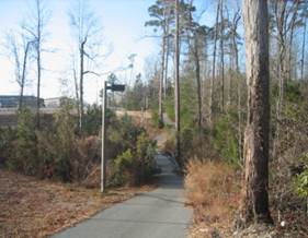
Continue to expand system of multi-use trails
Objectives:
Walking provides an alternative to vehicular use on base and results in reduced demand for roadway, parking and utility infrastructure, conserved resources and reduced vehicle pollution.
Provision of safe, convenient, accessible and well linked, enjoyable pedestrian ways encourages walking as an alternative to driving, improves physical fitness, and supports healthy well functioning Base community development and ATFP driven design.
Design Guidelines
Walkways shall be designed and implemented to establish a continuous network that is convenient, with direct routes between destinations. Establish pedestrian walkway connections to adjacent facilities, parking and roadway walk and multi-use systems at new and, over time, at existing developments.
Provide amenities including benches, receptacles, planting and lighting.
Walkways width shall be determined by function and scale of importance within setting.
· Troop Movement Walkways: four abreast shall be 10 foot width minimum.
· Major walkways: commonly traveled by two people abreast with frequent use and/or located in proximity to prominent building or open space setting shall be eight foot width minimum.
· Standard walkways: typical walkway use, single person, or two people abreast with lower frequency use shall be six foot width.
· Minor walk: infrequent, limited or local use, low volume shall be 4 foot width.
All roadways shall be designed with pedestrian walkways included in the cross section. See roadway sections for relationship of walks to roadways.
Crosswalks shall be provided at intersections and shall be 10 foot width minimum. Crosswalks shall be clearly marked by a consistent pattern of paint stripes or by crosswalk paving consistent with walkway paving material and contrasting to roadway paving.
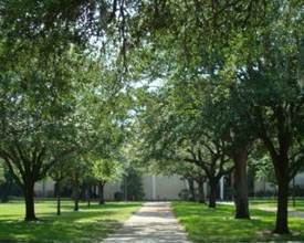
Walkways shall be provided with tree cover.
Walkways shall be planted with formal lines of shade trees to provide 50% shade coverage within 10 years of installation.
As trees mature, branches shall be limbed up to ensure eight foot minimum clearance between walkway surface and branching. For multi-use trails accommodating bicycles and pedestrians, clearance shall be 10 foot minimum. Trees shall be selected for appropriateness to setting and planted a minimum distance of five feet off walkways and trails, eight to 12 feet preferred as space allows, minimizing long term impact on paving. In tighter planting conditions, consideration should be given to installing root barrier at the walkway edge.
Multi-use trails and dedicated pedestrian walks intended for use after dark shall be lighted with special emphasis on lighting at intersections and vehicular crossings, destinations (building entries) and outdoor gathering spots. Bollard-style lighting is preferred at pedestrian ways as opposed to overhead lighting. Provide handrails and wall-recessed lights at outdoor pedestrian steps, ramps and stairs.
All pedestrian travel ways shall be universally accessible and in compliance with state and federal regulations, including Uniform Federal Accessibility Standards (UFAS) and Americans with Disability Act Accessibility Guide (ADAAG). Building access and general walkways should be designed to avoid use of stairways or grades requiring handrails when possible. When required, ramp access shall be integrated into the overall site/architectural design and shall not be a lesser means of access.
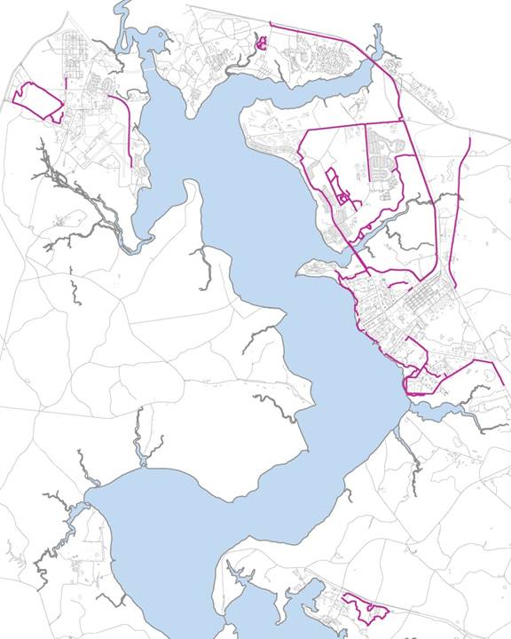
Existing multi-use trail network
Objectives:
Provide functional informal and formal outdoor spaces to enhance the quality of life, promote enjoyment of the outdoors, provide settings for passive, active, and ceremonial uses, and extend usefulness/flexibility of Base facilities and resources.
Establish a hierarchy of developed outdoor spaces related to buildings, circulation routes and Base open space to reinforce way finding, enhance entries and building functions, and spatially and visually unify the Base setting.
Design Guidelines
Provide plazas to create outdoor meeting and ceremonial spaces. Size and placement shall reflect functional needs and ceremonial importance to the setting. Consideration shall be given to flexible use of the space in choosing furnishings and establishing relationships –physical and visual- between the plaza and adjacent open space and buildings. Opportunities for extended views to and from plazas shall be considered.
Provide entry forecourts visible from the street and adjacent parking when actual building entries are not visible from these vantage points. Entry forecourts shall be located in proximity to buildings and connected to both parking and actual building entry/ies by pedestrian walkways. Entry forecourts visually reinforce circulation connections between vehicular and non-vehicular zones and visually link buildings to the surroundings.
Forecourts may serve as outdoor plazas, courtyards or smaller “landings” and be furnished with benches, shade structures, lighting, planting and distinctive architectural treatment and may include facilities for bicycle parking.
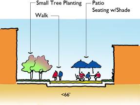
Provide courtyards as inviting outdoor spaces for informal gathering and relaxation.
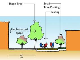
Broader spaces allow introduction of larger deciduous trees.
Provide courtyards as inviting outdoor spaces for informal gathering and relaxation and presenting pleasing views from building interiors. Courtyards should be furnished with seating and tables, and within residential settings may include bicycle parking. Courtyards shall be connected to adjacent building entries and area pedestrian walkway systems by pedestrian walks.
Scale outdoor use areas and select materials in response to adjacent buildings, open space and intended use. Outdoor use areas should unify the setting and visually connect to adjacent spaces.
For outdoor areas used after dark, provide lighting to enhance the use of the space, and create a sense of inviting security. All lighting shall be fully shielded, with full cut off fixtures controlling distribution of light used for sites adjacent to building windows.
Plazas, forecourt entries and courtyards shall be provided with minimum 50% shade cover. Shade cover may be provided by tree canopy, arbor planting, or permanent or temporary architectural device.
All plazas, entry forecourts and courtyards shall be universally accessible and in compliance with state and federal regulations, including Uniform Federal Accessibility Standards (UFAS) and Americans with Disability Act Accessibility Guide (ADAAG) and conform to UFC 4-010-01 DoD Minimum Antiterrorism Standards for Buildings
Objectives:
Provide varied and attractive open spaces for passive and active recreational use with established visual and physical connections between open spaces, building entries and exterior spaces, and circulation systems.
Preserve and enhance natural areas and resources.
The open space system is the overarching unifying element of the Base setting. Implement a Base-wide framework of “greenbelts” – broad bands of naturalized planting within stand-off zones (excluding unobstructed areas) - between roadways/parking (motorized) and building development (non-motorized) to establish a cohesive setting for Base facilities and activity.
Design Guidelines
Open space design shall reflect functional requirements of intended use, contextual setting of both adjacent open space and buildings and opportunities for connections to a broader open space system.
Parade grounds shall include traditional manicured lawn scaled for intended use (one acre per 125 persons) with area for reviewing stand (with capacity equal to five percent of total officer strength) and framed by walks and formal rows of trees at the edge.
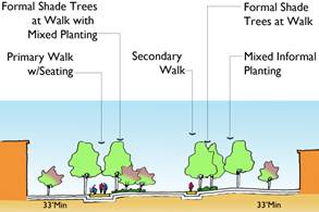
Informal Landscape
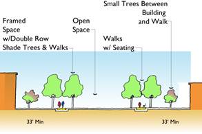
Formal Landscape
Design recreational open space, including fitness trails, sports fields, and picnic areas according to predominant intended use. Opportunities for multi-use and integrated design should be considered to maximize efficient use of available resources and create opportunities for increased sympathetic relationship between facilities.
Integrate children’s play areas and playgrounds into the open space setting and site in relationship to other supporting facilities such as residences, recreation fields, and schools. Design of these spaces should refer to UFC 3-210-04/1 Children’s Outdoor Play Area and UFC 4-740-14 Design, Child Development Centers.
Preserve natural open space to greatest extent possible during site development. Clustering development to maximize contiguous natural and developed open space shall be considered in all development projects.
Maximize opportunities to link existing and proposed open space elements and areas to establish contiguous and linking vegetative cover and open space.
Provide visual and physical connections to adjacent development and open spaces through managed sight lines, continuity of landscape (including planting) and circulation routes. Preserve view corridors into and from outdoor/open spaces.
Integrate and enhance existing natural settings into open space framework. Emphasis on preservation of natural resources (wetlands, shoreline, and wooded areas) and reduction in areas given over to highly maintained open space should be considered in all site design development.
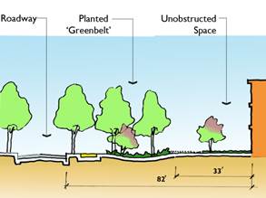
Implement a Base-wide framework of “greenbelts”
3.2.10 service areas
Objectives:
Provide for functional and efficient building and site service that is sited and designed to minimize negative impacts on adjacent uses including building, vehicular, bicycle and pedestrian circulation, and open space use.
Design Guidelines
Locate service facilities and loading docks to minimize visual and physical impact of access drives and actual service areas on adjacent uses such as public circulation ways, pedestrian crossings, building entries/facades and views from the building interior and outdoor use areas.
Combine service areas for multiple buildings to minimize access drives and duplication of facilities when possible.
Establish “service” access side of development areas to reduce conflicts between service and non service circulation.
Service area enclosure design should match the style and materials of adjacent architecture. Enhance integration of screening into surroundings with planting design.
For limited and controlled access service and emergency activity, such as utility maintenance or emergency access, within the stand-off zone, consider providing access through implementation of controlled access vehicular bearing pedestrian walks in order to clarify “pedestrian” environment, reduce duplicate paving and impervious surface, and maximize resources.
Provide appropriately designed paving cross section for intended vehicle use at service access and service sites. Dumpster enclosures and loading areas shall have reinforced concrete pads.
Design and location of service areas and related screening shall comply with ATFP requirements.
Objectives:
Establish best maintenance practices through programming, design and implementation practices that create well functioning, aesthetically pleasing facilities designed with consideration of long term durability, resource/energy efficiency, and reduced maintenance demand.
Establish planning and design practices that consider individual facility, infrastructure and site design projects in the planning context of the larger Base environment.
Establish a hierarchy of treatment zones and related allocation of resources, including funding for planned maintenance (based on life-cycle costs) at the time of planning and design for the project.
Refer to Appendix B - Common Operating Levels for descriptions of levels and map.
Design Guidelines
Reduce areas of mown turf throughout the Base. Increase proportion of site area established as naturalized planting and groundcover. Preserve and enhance areas of existing natural vegetation. Use native plant materials. Use of more formal mulched planting beds should be limited to locations that enhance main building entrances and ceremonial focal points.
Replace maintenance intensive and fussy plantings with plantings of long lived, drought-tolerant native plant materials. Focus planting on simplified designs dominated by trees and low ground cover materials.
Use durable, local materials (500 mile radius) in paving, site construction, and furnishings. See Appendix C - Regional Materials Radius.
Establish life-cycle maintenance budget at time of project implementation for planned maintenance funding.
RESTRICTIONS
While the Base strongly encourages Organizations to take advantage of the Self-Help program, the uniformity of Base appearance and regular maintenance must be considered. For more information, see Appendix F Summary Pamphlet. The Base restricts the following site and building modifications:
|
Description
|
Image
|
Alternative
|
|
Rope and wood post fencing
|
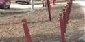
|
None
|
|
Unauthorized parking signs
|

|
Base Order permits marking paved surfaces
|
|
Landscape timbers
|

|
Landscape paver blocks
|
|
Exposed cable television cabling
|

|
None
|
|
Roof-mounted commercial and tactical antennas
|

|
Mount to side of structure, requires approval from Tower Working Group
|
|
Painted exterior stairways
|

|
None
|
|
Car ports or other covered storage
|
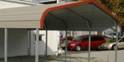
|
Work request for gazebo or picnic shelter
|
Objectives:
Establish stormwater management and Low Impact Development (LID) practices through programming, design and implementation that create well functioning, aesthetically pleasing facilities designed with consideration of long term functionality, and reduced maintenance demand.
Establish planning and design practices that consider individual facility, infrastructure and other site design projects in the planning context of the larger Base environment.
Design Guidelines
Comply with:
· UFC 3-210-10 Low Impact Development (Draft).
· North Carolina Department of Environment and Natural Resources (NCDENR) Coastal Stormwater Rules and Division of Water Quality design guidance for Best Management Practices (BMPs).
· LEED Site Credits SS6.1 and SS6.2.
· Energy Independence Security Act (EISA) Section 438.
Projects aboard MCB Camp Lejeune that create more than 10,000 square feet of built upon area will be required to be permitted through the North Carolina Department of Environment and Natural Resources (NCDENR). The NCDENR guidelines listed above provide the minimum technical requirements to obtain the State stormwater permit. Where feasible and compliant with future land use and/or master plan documents for the project area, consideration should be given for defining a project boundary and providing site design elements that comply with the NCDENR Low Density permitting requirements. In addition to the State stormwater permitting requirements projects that increase impervious area by 5,000 square feet will be required to comply with the Energy Independence and Security Act (EISA) Section 438, the Penn Memo and the Low Impact Development (LID) UFC.
The goals of LID are to create a developed site that closely maintains the natural hydrologic functions and conserves the maximum amount of the existing natural resources. The key elements of LID are custom site design, conservation, localized stormwater management, pollution prevention and hydrologic recharge of the local aquifer and/or adjacent wetlands. All of these elements work hand in hand to create an LID site design.
A custom site design will be required for each project so as to provide for all of the key elements of LID. A custom designed site shall provide for conservation by avoiding impacts to environmentally sensitive areas such as wetlands, ephemeral and perennial streams, and any required buffer areas. Where possible locate buildings, structures, parking/staging pavement, roadways, and the associated grading and earthwork operations outside of the above listed sensitive areas.
The custom site shall also provide for localized (i.e. decentralized point source) stormwater management controls or IMPs (integrated management practices) so as to facilitate the groundwater recharge as close to the original source through infiltration. Design shall provide for sheet flow of stormwater and avoid closed drainage systems or concentration of stormwater flow to the extent possible.
The infiltration will facilitate pollution prevention by filtering the ground water naturally while returning it to the local aquifer. LID and North Carolina requirements for infiltration to meet water quality requirements will vary and may require that the project exceed the less stringent requirement. In any case the State standard must be met in order to obtain the required permits.
Runoff beyond the requirement for infiltration should be directed (by surface flow if possible) to adjacent wetlands or streams as recharge these elements in a pattern as close to the original drainage pattern as possible. At a minimum, stormwater drainage shall be directed to wetlands or streams that match the original hydrology so as not to have a detrimental effect on the quality of the natural feature.
In addition to the above methods to meet the required stormwater quality and quantity requirements, the option of water reuse may be employed. Practices for stormwater reuse may include irrigation or a gray water system for non-potable use.
The designer shall take care in selecting stormwater management and LID practices to ensure that they are in compliance with the NCDENR requirements for the classification of the downstream receiving waters. Certain classifications greatly restrict the allowable stormwater management options.
Maintenance of the selected BMP, IMP or rainwater collection and reuse system is critical. Designer shall coordinate with MCBCL personnel as to acceptable practices to ensure the proper maintenance can be provided. Any measure that is employed shall be required to provide an O&M Manual detailing the proper maintenance requirements and schedule.
The LID principle to minimize the development footprint shall not be used to significantly reduce or eliminate active open space from a project. These areas may include parade decks, formation areas, active recreation areas or other site open space amenities. These project elements are vital to the function of the facilities and Marines that they serve and should be maintained in the site design of the project. Economies may be found in multiple building projects where these active open space amenities may be combined and possibly reduced in scale while maintaining the intended function.
Surface discharge of rainwater collected from roofs at grade, although a LID technique, must be carefully designed to avoid overwash of the surface at the base of downspouts. Rainwater discharge should be diverted to lower-rate conditions that avoid eroding topsoils and mulch, such as discharging onto gravel areas. Surface discharge on north sides of buildings should be conveyed to a minimum distance of six feet away from buildings, to avoid creating damp soils next to building facades that receive little or no sun to dry out.
In addition to proper stormwater management techniques, proper erosion and sediment control shall be considered for all land-disturbing activities. Use of centipede sod is required for all permanent restoration of disturbed areas that are not otherwise built upon, paved or planted. Sod or other intense turf-planting techniques such as erosion control blankets and sub-surface geogrid reinforcement for turf may also be appropriate for enbankments and other sloped areas. Historically, conventional seeding techniques have met with low success on construction sites and are easily disapproved by NCDENR as ineffective.
The extent and type of architectural treatment on the Installations will vary. However, there shall be a common thread or theme in place to tie the Special Districts together and the Installation as a whole. The creation of place, or the urban imageability, is the experiences of inhabitants as they go from place to place and unconsciously recognize prevailing architectural images throughout the Base. The approach of all individual projects, whether new or renovation, should promote the overall improvement in appearance of the Installations.
The buildings at MCB Camp Lejeune and MCAS New River demonstrate a cohesive theme within most of the special districts. Some areas have less historical context, were developed during various eras of architectural fashion, or hove no defined style because they are newly developed. The BEAP is a tool to bring together a visual continuity and to define the architectural standards for future design, construction and maintenance projects.
3.3.1 ARCHITECTURAL STYLE AND ROOF FORMS
The architecture designs at MCB Camp Lejeune and MCAS New River can be grouped into four major categories:

Early American styles: this consists of Georgian, Colonial Revival or Federalist styles
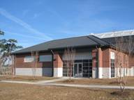
Contemporary style: interpretations and adaptations of vernacular and classical design elements
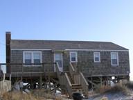
Shingle style: large expanses of unpainted shingles, porches, and window clustering

Utilitarian: devoid of any discernable style of architecture, strictly functional in form
The following diagrams describe the roof forms used throughout this document:
|

|
Gable
|
|

|
Hip
|
|

|
Gable-on-hip
|
|

|
Mansard
|
|
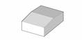
|
Low slope
|
|

|
Shed
|
Color charts define the permissible materials and colors for each district. The following diagram clarifies how the color chart is read:
Color

Material

Color charts must be used in conjunction with the color boards; see Appendix E – Color Boards.
The guidelines in this document use as number of architectural terms to identify specific element of a building facade. The following diagrams clarify these terms:


|
Description
|
Hadnot Point
Hospital Point
Wallace Creek
Cogdels Creek
|
French Creek
|
Courthouse Bay
|
Paradise Point
|
Onslow Beach
|
Camp Geiger
|
|
Architectural Style
|
|
|
|
|
|
|
|
Georgian
|
yes
|
no
|
no
|
yes
|
no
|
no
|
|
Colonial Revival
|
yes
|
no
|
yes
|
yes
|
no
|
no
|
|
Shingle
|
no
|
no
|
no
|
no
|
yes
|
no
|
|
Contemporary
|
no
|
yes
|
yes
|
no
|
no
|
yes
|
|
Utilitarian
|
no
|
no
|
no
|
no
|
no
|
no
|
|
Roof Form
|
|
|
|
|
|
|
|
Low slope
|
no
|
no
|
no
|
no
|
no
|
no
|
|
Gable
|
no
|
yes
|
yes
|
yes
|
yes
|
yes
|
|
Gable-on-hip
|
yes
|
no
|
yes
|
yes
|
no
|
no
|
|
Shed
|
no
|
no
|
no
|
no
|
yes
|
yes
|
|
Mansard
|
no
|
no
|
no
|
no
|
no
|
yes
|
|
Hip
|
yes
|
yes
|
yes
|
yes
|
yes
|
yes
|
|
Description
|
New River
|
Stone Bay
|
Camp Johnson
|
Entry Gates
|
Industrial
|
Airfield
|
|
Architectural Style
|
|
|
|
|
|
|
|
Georgian
|
no
|
yes
|
no
|
yes
|
no
|
no
|
|
Colonial Revival
|
no
|
yes
|
yes
|
yes
|
no
|
no
|
|
Shingle
|
no
|
no
|
no
|
no
|
no
|
no
|
|
Contemporary
|
yes
|
yes
|
yes
|
no
|
yes
|
yes
|
|
Utilitarian
|
no
|
no
|
no
|
no
|
yes
|
yes
|
|
Roof Form
|
|
|
|
|
|
|
|
Low slope
|
no
|
no
|
no
|
no
|
yes
|
yes
|
|
Gable
|
yes
|
yes
|
yes
|
no
|
yes
|
yes
|
|
Gable-on-hip
|
no
|
yes
|
no
|
yes
|
no
|
no
|
|
Shed
|
yes
|
no
|
yes
|
no
|
yes
|
yes
|
|
Mansard
|
no
|
yes
|
no
|
no
|
no
|
no
|
|
Hip
|
yes
|
yes
|
yes
|
yes
|
no
|
no
|
Building entrances serve an important role in a building's appearance and function and should play a prominent role in the building's facade. Entrances on new buildings should be clearly defined through formal, spatial, and/or material hierarchy and constitute a clear point of entry.

Primary entrances shall be proportional to the building mass. In three and four story buildings, entry elements shall be at least two stories in height. In five story buildings, entry elements shall be at least three stories in height.
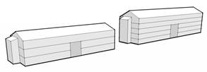
Entry elements shall be sized proportionately to building height
On historic buildings, entrances should be preserved, rehabilitated, and restored back to their original configurations wherever possible, or reconstructed to replicate the original appearance. Seek guidance from Camp Lejeune Environmental Management Department prior to any work on individual buildings and historic districts. Specific guidelines may be found in a document available from Environmental Management:
Historical Architectural Evaluations, Marine Corps Base Camp Lejeune, Onslow County, North Carolina (Bowers, Dixon, and Jacobe 2008)
3.3.5 BUILDING ADDITIONS AND RENOVATIONS
All building additions or renovations should be compatible in aesthetics, scale, form, material, orientation, and style with the existing building. Incompatible additions and renovations should be removed and replaced with more compatible designs that are more sensitive to the building style, use, and location. In cases where removal and replacement is not obtainable, incompatible additions and renovations should be modified to make them more compatible with the building style.
3.3.6 GUIDELINES FOR HISTORIC BUILDINGS, HISTORIC BUILDINGS PRIORITY TREATMENT
The historic buildings on the Installation play a prominent role in the overall quality and character of the Base. They are protected by virtue of established historic districts in order to preserve MCB Camp Lejeune's rich history and culture. Additions and renovations to historic buildings should conform to the guideline document noted above, as well as the State Historic Preservation Office. Incompatible modifications should be removed or enhanced to become compatible with the building. Routine maintenance should constantly be provided to protect structures from deterioration, and any new buildings in the historic districts should conform to the prevalent style. Structures in historic districts proposed for demolition, no matter how insignificant, must be approved by Base prior to demolition. See Section 2.6 Historic District Overview.
Objectives:
Preserve and enhance existing landmarks and focal points and, as opportunities occur, establish additional elements to reinforce Base identity and assist in spatial orientation and way finding.
Design Guidelines
Existing landmarks and focal points shall be preserved and enhanced through control and preservation of sight lines, enhanced planting framing the view and consideration of dynamic process of the viewing sequence.

Focal point and landmarks reinforce Base identity and assist in spatial orientation and way finding
The views to landmarks and focal points and their immediate settings should be designed and maintained to eliminate or screen elements that are distract from, obstruct or reduce the prominence or importance of the view to the landmark or focal point.
Consider introduction of new focal points within the context of the prominence of the facility, the intended viewer (motorist, pedestrian) and viewing sequence, and the need for symbolic orientation.
Objectives:
Present, preserve and maintain existing and newly implemented memorials, monuments, statues, and displayed elements honoring people and events in a means that dignifies the remembrance and inspires respect.
Memorials, monuments, statues, and displays communicate the history, identity and culture of the Marines and Base.
As a means of conveying meaning from one generation to the next, memorials, monuments, statues, and displays should be integrated into meaningful locations and be accessible.
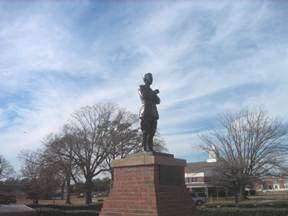
Monument of John A. Lejeune at the Hadnot Point roundabout
Design Guidelines
Select settings for memorials, monuments and displays so as to be respectful of the element, provide appropriate scale to the element’s size and importance, and potential for integrating the setting into the larger surroundings.
Consider the experience of approaching and viewing the monument or memorial close up to maximum benefit. Orient the memorial in a direction to be seen by the majority of viewers. Raise memorial above the adjacent ground plane on plinth or base for better display.
For sites with multiple related memorials, arrange memorials as part of an overall composition rather than as single isolated unrelated elements within the space.
Locate memorials to enhance the selected site, courtyard or plaza.
Select monument and memorial materials for long term quality of appearance and durability.
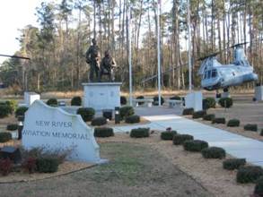
Displays communicate the history, identity and culture of the Marines and Base
Settings for displays such as ships, planes or equipment shall provide prominence for the elements and opportunity to fully appreciate the elements from varied aspects of viewing.
Mounting and installation methods should be designed specifically for the particular element to best display the object by tilting, suspending or anchoring in the most striking or noticeable means, assure secure support, and allow easy access for maintenance of the object.
Exhibit area should be laid out and maintained with crisp detail appropriate to displays with a simple defined “base” flush or raised and cleanly edged with accompanying ground mounted identification plaque in explanation.
Displayed objects should be exhibited in a way to avoid confusion with operational equipment.
Consider presentation of memorials, monuments, and displays in both day time and night time settings. If area is viewed at night, include appropriate lighting either as part of the overall area site lighting or as special lighting to ensure that the face of the memorial/monument or object of display is not cast in shadow.
Objectives:
Present flags in a meaningful, highly visible, and consistent way to express national and service pride, and as focal element, assist in orientation and way finding.
Design Guidelines
Flagpole design shall be consistent throughout the Base.
Flagpole design shall be consistent throughout the Base. National Flags are authorized on the basis of one per Organizational Flag. See Marine Corps Order P10520.3B for a list of authorized organizations.
Limit flagpoles to major command and landmark locations. Flagpoles may be grouped to signify the importance of a location or the primary nature of the main gateway.
As with other focal elements and landmarks, avoid visual conflicts with elements such as signage, poles, and utility structures that detract from or obstruct the view of the flag(s).
Site flagpoles to allow respectful observation in the immediate area with adequate space at the base for raising and lowering, unfolding and folding the flag.
Flagpoles should be attractive, durable, and easily maintained. Aluminum poles are recommended. Halyards shall be accessible and operable. The flagpole shall be mounted in reinforced concrete footing designed to withstand wind load based on height of pole, maximum sized flag to be displayed, and local conditions.
Provide site lighting for those flags that remain raised after sundown.

Flagpole outside the Base Headquarters Building
Objectives:
Planting, in particular tree planting, provides one of the most effective means of establishing continuity and unification of the Base setting by framing spaces, linking areas, reinforcing way finding, and, over time, establishing a long lived and memorable setting for Base activities.
Establish an ordering of outdoor spaces that are clearly defined and perceived as a whole.
Increase planted area and tree coverage to provide greater physical comfort for users and thereby encourage greater outdoor activity, reduce solar heat gain and glare, and storm water management demand.
Design Guidelines
Preserve and protect existing healthy, long-living trees. Natural areas, including shoreline, wetlands, and wooded areas, should be preserved and protected. If development requires site disturbance, care shall be taken in layout to preserve the greatest contiguous and/or continuous linear natural and naturalized areas. Avoid development planning resulting in small “islands” or isolated pockets of vegetated land.
Plantings should be appropriate to the scale and setting of their surroundings. Plantings should be composed as large masses and regularly spaced rows rather than as fussy collections. The overall character to be achieved by plantings is one of tranquil order and restraint.
Planting design shall reinforce the physical structure of the Base and help to delineate streets, walks and open spaces.
For walkway, plazas, terraces or other hard surface outdoor gathering areas not otherwise shaded, plant trees so that so that a minimum 50 percent shade cover is provided 10 years after installation.
For parking areas provide 15 percent minimum shade coverage measured 10 years after installation of trees. Within the parking limits, provide pervious planting bed equal to or greater than five percent of the total square footage of paving area.
Where space permits and ATFP requirements allow, use plant materials in informal multi-height plantings to screen undesired views including parking and storage areas, service courts and trash enclosures (not architecturally treated) and substations. Planting screens shall have a natural composition and tie into the overall landscape setting.
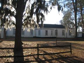
Integrate natural settings and planting. Reduce areas of mown turf.
Reduce areas of mown turf throughout the Base. Increase proportion of site area established as naturalized planting and groundcover alternatives to mown lawn. Preserve and enhance areas of existing natural vegetation. Use native plant materials. Use of more formal, permanent mulched planting beds requiring higher maintenance should be limited to locations that enhance main building entrances and ceremonial focal points. As a note, this is distinct from mulch required in establishing long term naturalized and groundcover areas (as alternative to lawn).
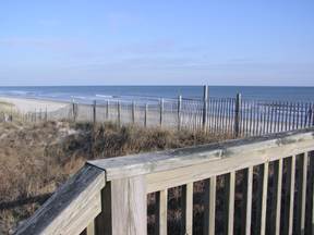
Protect and enhance the stability of the natural environment.
Avoid soil and beach erosion by establishing plant cover on steep slopes and exposed areas.
Plant Selection:
Plants shall be selected based on appropriateness to micro-climatic and soil conditions of the site, including stress of human impact; and ease of maintenance once established.
When turf is specified or required, Centipede sod shall be used.
Mature size and form of plant material shall be considered in developing planting design. Design should allow plants to be maintained in their natural form with minimal pruning at mature size and as appropriate for the setting. Microclimate, soil and adjacent activity and utilities should be considered in selecting materials. For example, selection of shade trees for walkways should favor deeper tap root species to reduce impact to adjacent structures.
See Appendix D Plant Palatte.
Irrigation:
Irrigation of lawns is not intended as a general practice on Base. Exceptions to this rule may be made for designated playing fields in recreational areas.
During establishment, trees shall be provided with temporary watering, for example through use of “gators” or by water truck.
Consider captured rainwater, recycled wastewater, cisterns, and detention ponds for use in supplementary watering.
Objectives:
Provide an effective, attractive, unified “family” of signage types to communicate information with clarity, in a manner that:
· Enhances the identity of the Base,
· Assists in providing directional way finding to one’s destination,
· Identifies buildings, landmarks, streets and parking areas, and
· Conveys regulatory information.
Establish a Base wide approach to locating signage so that information is communicated concisely and extraneous sign usage is minimized.
Design Guidelines:
General Guidelines
All signage shall comply with the Sign Policy for Marine Corps Base Camp Lejeune, Base Order 11014.3, dated 28 August 2003.
Letters
Letter font shall be Helvetica Medium in upper and lower case. The first letter of every word and acronyms shall be uppercase. Letter color shall be white. The exception to this standard shall be made for entrance signage. Letter font for mounted letters on entrance signage shall be Times Medium, upper case, of stainless steel.
Spacing for words and letters shall be “normal”. Spacing between lines of text shall be consistent among signs at one-half the height of the letters.
Words (lines of text) shall be positioned left justified.
Arrows on signs shall be white and conform to a square proportions illustrated below. Group destinations to share common directional arrow. Use graphic symbols rather than words when possible to convey messages quickly and concisely.
Design the letter and arrow size in accordance with the design speed of the viewer.
· Less than 25 miles per hour (mph) – 4 inch lowercase letter and arrow shaft height.
· 26 – 35 mph – 6 inch lowercase letter and arrow shaft height.
· 36 to 45 mph – 8 inch lowercase letter and arrow shaft height.
· 46 to 60 mph – 10 inch lowercase letter and arrow shaft height.
Adjust the designated letter size in accordance with the following guidance:
· 150 foot reading distance – minimum 4 inch lowercase letter height.
· 200 foot reading distance – minimum 6 inch lowercase letter height.
· 300 foot reading distance – minimum 8 inch lowercase letter height.
· 400 foot reading distance – minimum 10 inch lowercase height.
· Increase the lowercase letter height 1inch for every additional 50 feet or part thereof.
Placement:
Place signs to allow full unobstructed viewing. Avoid placing behind obstructions such as utility poles, lighting, vegetation, furnishings, or other signage.
Place signs a minimum of two feet and maximum of six feet from the roadway and minimum of two feet from walkways or multi use paths. Adjust distance according to site conditions and viewing speed – the slower the speed the closer the sign to the edge of travel way.
Position the bottom of the sign letters at minimum of 30 inches above the ground for vehicle design speeds of 30 mph or slower, and 36 inches above the ground for design speeds above 30 mph. Signage directed toward pedestrians or bicyclists shall be a minimum 24 inches above the ground and maximum height of 4 feet-6 inches to top of sign.
Function Specific Sign Guidelines:
Entrance Signs
Entrance signs include: exterior entrance signs located at the main entrance and secondary entrances to the Base; and interior entrance signs, located at entrances to special districts of the Base.
Exterior entrance signs shall use brick and concrete. Messages and graphics shall be mounted graphics of stainless steel (light color on dark brick for legibility). The overall form of the sign shall be horizontal.
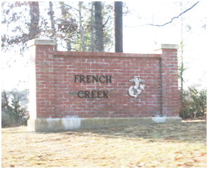
Typical entrance sign announcing French Creek

Locate entry signage to the right of the entry drive.
Planting should augment the horizontal nature of the signage and should integrate the sign as part of a larger site design and as such shall be composed of naturalized massings (trees and shrubs) extending out from the sides of the sign and forming a visual backdrop. Planting shall not obstruct the view to signage.
Consideration should be given to appropriate night lighting for entrance signs and entry area – preserving legibility of the message and associated graphics.
Directional Signs
Directional signage is located at pedestrian and vehicular decision points to assist in way finding.
Locate directional signs (vehicular or pedestrian way finding) at decision points. Signs should not proliferate along a route.
Directional signs shall be placed perpendicular to the travel way.
Group destinations to a single arrow.
Highlight visitor information (for example, parking symbol)
Identification Signs
Identification signs identify building use, landmarks, parking area designations, etc.
Buildings shall be identified by bold numbers for visitors and public safety crews (light letters on dark background). Building numbers shall be mounted at prominent corners, seven feet above ground surface (or as appropriate in relationship to building features), facing street or emergency vehicle access/pedestrian approach. Provide additional signs as required for larger buildings and those located on corners.
Parking area designation/identification signs shall be located in logical sequence with way finding system on drive approach to the parking area. Follow general guidelines for lettering related to viewing from a vehicle. Message shall include: name/number of lot, allowed users, permit/decal requirements, hours of enforcement and allowed parking duration. Special consideration shall be given to signage placement and layout of message (use of graphic symbol) for visitor and handicap parking way finding and designation of parking spaces.
Street
Used to identify streets by name and provide locational reference.
Street signs for general use shall be green with white lettering and Marine Corps seal in representative colors to the left of the street name. Signs shall be mounted on square tubular galvanized steel posts painted black, with bottom of sign set seven feet above finished grade.
Street signs within camp districts shall be similar to existing concrete pillar signs traditionally found at Camp Geiger and Camp Johnson. Letters shall be black stenciled Helvetica medium continuous.
Regulatory
Regulatory signage includes traffic signs; and custom postings, warnings or military regulations. Regulatory signage should conform to U.S. Department of Transportation Manual of Uniform Traffic Control Devices for Streets and Highways.
Regulatory signage shall be mounted on square tubular galvanized steel posts painted black. Backs of regulatory signs shall be painted black.
Changeable (Digital or Board)
Changeable message signage (digital or board) is typical used outside community support facilities indicating activities or special events. Background shall be black/dark with white/light colored letters. Use of this sign type should be limited to specific programmatic locations.
Digital signs are prohibited from having blinking or moving graphics and are only approved for use at formal school entrances and command buildings.
Objectives:
Consistent paving differentiated by function provides clarity to circulation and contributes to safety.
Materials shall be attractive and durable. Use of permeable paving to reduce run off and light colored paving with high albedo to reduce heat island affect are encouraged.
Design Guidelines:
All walks shall be paved with scored concrete, tooled edges, light broom finish perpendicular to direction of travel. Cross slopes shall not exceed two percent.
When connecting to an existing walk, saw cut the existing walk at the control joint, meet and blend grade of new walk to existing. Implement consistent scoring pattern with each segment of new walk.
Provide detectable warning strip at base of ramps, and at flush meeting of vehicular and walk surfaces as required by Americans with Disability Act Accessibility Guide (ADAAG). Detectable warning strip shall be precast concrete or manufactured detectable warning concrete paver.
Materials:
Roadways and parking areas (typical):
· Bituminous concrete
Special vehicular areas including ceremonial drives, drop-offs, car courts, and parking areas:
· Concrete pavers (light grey mix)
· Permeable pavers (light grey mix)
Emergency drives through open space/landscape:
· Concrete scored as walkway (w/ reinforced lawn to provide additional required width)
· Concrete pavers light grey mix (w/ reinforced lawn to provide additional required width)
· Reinforced lawn
Bicycle lanes (within roadway)
· Bituminous concrete with blue painted markings
Walkways, Courtyard, Plazas:
· Scored concrete (typical)
· Scored colored concrete (light warm grey)
· Concrete pavers (light grey mix)
· Do not paint concrete or paver walk, stairs or other pedestrian areas.
Multi-use pedestrian/bicycle way:
· Scored concrete (typical within developed areas when used in combination as a sidewalk)
Recreational multi-use trail:
· Bituminous concrete (Use of permeable paving is encouraged.)
Crosswalks
· Consider use of scored concrete as continuation of walkway for greater visual definition of pedestrian travel/crossing for aesthetic and traffic calming in higher visibility or trafficked areas.
· At minimum crosswalk shall be 10 foot width with 12 inch width painted bars.
Objectives:
Consistent use of a selected family of site furnishings throughout the Base reinforces Base identity and provides greater flexibility and efficiency in reuse, addition, and maintenance.
Furnishings shall be attractive, durable and present an image of permanence and quality.
Use of common finishes and colors, especially consistent use of black for all metal and plastic coated metal will lend to a more refined look that will tie dissimilar elements together during a phasing implementation, ease in matching furnishing purchased over time, and present a fitting color for varied architectural styles, and understated integration into the landscape.
Design Guidelines
ATFP Devices
Bollards
· Black powder coated galvanized steel finish in removable and permanent styles. May be combined with low level bollard lighting. Two forms; ornamental bollard for formal and high profile settings and simpler concrete filled steel post painted black.
· Low fencing as pedestrian or edge definition. Bollards may be combined with steel cable or chain for restricted edging, though other longer lasting, less obtrusive alternatives may be considered such as curbing or grade change.
· Avoid use of wood posts/bollards and rope as these are not durable, nor do they maintain their appearance over time.
Benches and Tables
· Black powder coated galvanized steel mesh tables and chairs (movable) for residential courtyards and outdoor dining patios, may be combined with table umbrellas for shade to encourage use during warmer months.
· Black plastic coated steel mesh picnic tables for use in recreational and casual outdoor settings.
· Black plastic coated metal mesh bench for use throughout Base.
In addition to benches, tables and chairs, consideration should be given to incorporating informal seating opportunities in site design through use of seat walls, broad “landscape” steps, and gentle slopes facing onto active use areas such as play fields or waterfront.
Bicycle Racks:
· Galvanized powder coated black “bike hoop” design.
· Alternative: “Lightning Bolt” rack which is straightforward to install at new and pre-existing paved sites, has a low profile, may be double loaded, and is efficient in layout.
Trash Receptacles:
· Black powder coated galvanized steel mesh with removable cover. Provide receptacles as required for trash collection/recycling programs.
Drinking Fountains
· Black powder coated galvanized steel with stainless steel bowl. Simple post and bowl design with paving at base to prevent ground rutting from runoff.
Planters:
· Concrete or cast stone with natural finish pots and cast planter boxes.
· Pots: Use in formal line or clustered in group with varied sizes. Within furnishing family identify three sizes. Planting within pots should be equal or greater than height dimension of pot. For possible use as ATFP barrier.
· Boxes: Use as architectural edge to space, for example, at formal plazas or in courtyards. If an extension of building design, finish may be chosen to match architectural finish and style. For possible use as ATFP barrier.
· When locating planters, consider ability to maintain planting, including availability of water and intensity of sun and pavement heat. Consider drip irrigation for permanent planters.
Shelters
· Bus: Simple covered shelter, black finished metal with seating. If side walls are provided use clear “see through” walls to minimize visual impact and allow open view within and from outside. Consider solar roof options for providing shelter lighting.
· Recreational: Pavilion like steel structure. Consider local conditions, wind load and footing requirements. Provide concrete walkway paving for area under shelter.
Objectives:
Provide fencing to secure perimeter, enclose recreation areas, mark boundaries, and restrict movement between areas (vehicles and /or pedestrians). Additionally, fencing may be used in screening alone or in combination with planting.
In general, fencing should be understated, functional and durable, and should not detract from the setting.
Walls should be an extension of architectural treatment and materials of the region.
Design Guidelines
Ornamental steel picket fencing: Fencing in visually prominent areas such as gateways, administrative areas or near housing should be simple, ornamental, black steel square picket fencing. Chainlink fencing is prohibited as ornamental fencing.
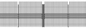
Ornamental steel picket fencing
In more commanding settings such as primary entry gateways, set fence on a brick faced base. In common settings where the fence is aligned through lawn or groundcover, a concrete “mow strip” base (flush or curbed) may be used for ease of maintenance at the base.
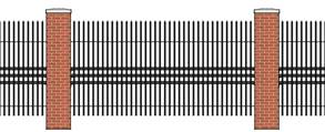
Fencing appropriate for commanding settings
Perimeter chain link fencing: Black chain link for use in low activity, less visible perimeter and service areas may be used in combination with planting to provide screening buffer and integration into the landscape setting.
Stormwater management pond fencing: Four foot high black chain link fencing shall be provided for stormwater management ponds with water depths greater than 18 inches. Fencing may be supplemented with adjacent planting to naturalize and integrate pond within the surroundings.
Architectural walls: Walls of materials related to adjacent architecture become an extension of the architecture into the site and may be used to enclose and/or screen undesirable views or restrict access.
Objectives:
Locate utilities and provide related site improvements to minimize visual impact, provide efficient, well functioning utility services, and allow for ease of maintenance and repair.
Design Guidelines
Utility corridors and individual lines shall be located to minimize facility disruption or long term damage during repair or maintenance.
· Recommended utility corridor alignment: Locate utilities under pavement or within areas intended to remain open lawn in order to allow effective restoration of surface conditions immediately following excavation due to repair or maintenance.
Group utilities as possible to minimize extent of land affected. Site above grade utilities, transformers and other structures to avoid or minimize visual impact.
· Avoid aligning utilities within intended mixed planting areas, tree planting zones, and preserved natural areas in order to limit long term destruction caused by utility repair or maintenance.
Dumpsters should be conveniently located to the facility they serve, and away from main roads, entrances, and sidewalks. When possible, landscape treatments should be used to help screen dumpsters.
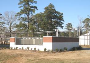
Utility Enclosure
Specifications:
Dumpster areas should be located on concrete pads with adequate radius, approach length, and overhead clearance from trees, utilities, and structures. Screening should be provided on three sides by a 7 foot tall masonry wall to block views of the containers. The dumpster enclosure's materials and style shall complement the facility it serves.
· Where possible, orient the openings of enclosures away from building entrances and main streets.
- Locate dumpsters to minimize visual impact and comply with force protection standards.
- Provide protective bollards to protect screen wall.
- Where appropriate, design enclosures as part of service areas for new facilities.
- Provide concrete pads and access aprons in front of enclosure entrances.
- Include landscaping and provisions for pedestrian access.
Dumpster Pad sizes for Camp Lejeune are as follows:
· Single dumpster: Sixteen feet wide and nine feet deep.
· Double Dumpster Pad: Twenty-seven feet wide and nine feet deep.
· Triple Dumpster Pad: Thirty-eight wide and nine feet deep.
· Four Dumpster Pad: Forty-nine feet wide and nine feet deep.
· Five Dumpster Pad: Sixty feet wide and nine feet deep.
Objectives:
Site lighting should enhance the nighttime environment, assist in way finding and orientation, contribute to safe movement, and establish a sense of security.
Design Guidelines
Provide an increased clarity and sense of security using light to define the edge of open space and parking areas. Avoid lighting open spaces and parking areas from the center. Edges left in shadow decrease the sense of security in the night time setting.
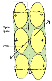
Light spaces from the edges rather than the center.
Arrange lights opposite each other, or on narrower roadways light from one side only, to reinforce the direction of circulation and increase clarity of roadways at night. Avoid staggered patterns of light. This pattern works against the creation of a regular rhythm and ordering of the corridor.
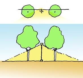
Coordinate lighting and planting design.
Lighting design should avoid conflict with the foliage and shadows of maturing trees and should provide good uniformity and vertical illumination.
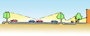
Provide a hierarchy of lighting effects.
Aid drivers and pedestrian circulation by providing a hierarchy of lighting affects that correspond to the different zones and uses of the site. Provide highest light levels at the destination (building entry), crossings and decision points (intersections).
Minimize glare and obtrusive light by limiting outdoor lighting that is misdirected, excessive, or unnecessary. Establish use of cut-off and fully shielded fixtures to control distribution of light.
Incorporate lighting curfews (i.e. turn off select lights automatically after a certain hour, such as when businesses close or traffic is minimal).
Lighting Pole Heights
· Roadway and Parking Area : 20 to 25 foot height (at secondary and tertiary roads that are one lane each direction may be 14 to 16 foot height)
· Walkways, Plazas and Courtyards: 12 to 15 foot height
4.0 DESIGN GUIDELINES FOR SPECIAL DISTRICTS
The Common District guidelines are intended as the default guidelines for all areas within the Installation which do not fall in a Special District or otherwise do not require unique consideration. These areas are illustrated below. BEQs have unique requirements which are outlined in Section 4.1.2.


Areas shown that do not fall within a Special District and therefore default to the Common District. Remote sites also fall under the Common District guidelines, such as Oak Grove OLF.
Massing
Building mass shall be based on the historical context of Camp Lejeune, primarily the Georgian and Colonial Revival styles. Symmetry in building mass, windows, and roof shall be a large determinant of design.

Allowable roof forms are gable-on-hip and hip at slopes between 4:12 and 6:12.
Windows and Entrances
Windows and entrances shall be designed to match the historic character seen in Georgian and Colonial Revival buildings throughout Camp Lejeune. Window dimensions shall fall within a range of 1:1.6 to 1:2 ratio of width to height, as shown in the diagram below.

Window heads and sills shall be detailed to avoid a punched opening affect. This can be accomplished with different types of lintels which blend with the historic character, such as precast concrete or stone or jack arch. Sills may be precast concrete (preferred) or special brick shapes.

(Left) Example of window head using soldier coursing; (Right) Example of precast concrete sill
Entry elements for the primary entrance shall be proportional to the building mass. In two story buildings, entry elements shall be greater than half the height of the building. In three and four story buildings, entry elements shall be at least two stories in height. In five story buildings, entry elements shall be at least three stories in height.
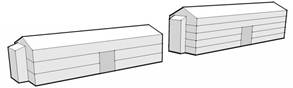
Entry elements (shaded) for three and five story buildings
Entrances shall provide some type of weather protection, such as a pocketed door or canopy. Entrances must be formal, clearly identifiable and located toward the most common approach, preferably facing the public way or open space.

Body and Roof Materials
All facades shall be face brick, modular size. Base foundations shall be architectural concrete block.
Roofing shall be standing seam metal with high standing seams between 12 and 18 inches on center.

Colors common
Description
|
Color
|
|
Facade
|
|
|
Building body
Screen walls
|

red flashed smooth
standard gray mortar
|
|
|

red flashed wire cut
standard gray mortar
|
|
Base foundation
|

white split face
white mortar
|
|
Metal Panel
|

sandstone
BM: OC-48
PANTONE: 400
FED STD: 17875
|
|
Painted Surfaces and Factory Finishes
|
|
Exterior stairs
Utilities/equipment
Appurtenances
|

slate gray
BM: 2133-40
PANTONE: 444
FED STD: 36173
|
|
Gutters/downspouts
Fascia/soffit/frieze
|
sandstone
BM: OC-48
PANTONE: 400
FED STD: 17875
|
|
|

bone white
BM: 2140-70
PANTONE: 9041
FED STD: 37875
|
|
Handrails
|

clear anodized aluminum
|
|
Entry accents
Doors
Window/door trim
|
bone white
BM: 2140-70
PANTONE: 9041
FED STD: 37875
|
|
|
clear anodized aluminum
|
|
Roof Cladding
|
|
|
Metal roof
|
sandstone
BM: OC-48
PANTONE: 400
FED STD: 17875
|
Details
Common District details shall be designed according to the early American architecture that is the prevalent style on Camp Lejeune, which includes elements of Georgian and Colonial Revival. Detail commonly associated with these styles includes:
· Brick quions
· Base foundations to water table line
· Molded cornices

Building 15 demonstrates details common to the Georgian and Colonial Revival styles: white base foundation, brick quoins, and embellished cornice

Molded cornice detail found in Georgian styles on Base
Proportion of the water table line and the height of the cornice detail to the overall building height shall be carefully controlled such that the respective dimensions of these elements are as follows:

The gable end on a gable-on-hip roof shall be equal in height to 1/3 of the overall roof height.
Training facilities include enclosed buildings, observation towers, shelters, or any permanent vertical structure which serves a training function. Generally, training facilities shall follow closely to the Greater Sandy Run District guidelines (Section 4.14). Colors and materials shall be the following:
Colors TRAINING FACILITIES
Description
|
Color
|
|
Facade
|
|
|
Building body
Screen walls
|

gray split face
standard gray mortar
|
|
Metal Panel
|
sandstone
BM: OC-48
PANTONE: 400
FED STD: 17875
|
|
Painted Surfaces and Factory Finishes
|
|
Exterior stairs
Utilities/equipment
Appurtenances
|
slate gray
BM: 2133-40
PANTONE: 444
FED STD: 36173
|
|
Gutters/downspouts
Fascia/soffit/frieze
|

evergreen
BM: 2040-10
PANTONE: 7484
FED STD: 14109
|
|
Handrails
|
slate gray
BM: 2133-40
PANTONE: 444
FED STD: 36173
|
|
Entry accents
Doors
Door trim
|
evergreen
BM: 2040-10
PANTONE: 7484
FED STD: 14109
|
|
Window trim
|
bone white
BM: 2140-70
PANTONE: 9041
FED STD: 37875
|
|
Roof Cladding
|
|
|
Metal roof
|
evergreen
BM: 2040-10
PANTONE: 7484
FED STD: 14109
|
|
Composition shingle
|

slate gray
|
Bachelor Enlisted Quarters (BEQ) require special consideration with regard to architectural design. This is primarily due to their abundance throughout base and the large visual impact BEQs have on a site and district. Often these buildings are four or even five stories and clustered together, making them a predominant feature regardless of location.
Careful massing of BEQs is critical. Forms shall be designed to evoke the early American styles of the installation, as well as be visually rich. The complexity of massing in the diagram below brings the scale of the BEQ to a human level, as well as break up its large silhouette against the site.
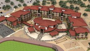
This BEQ design for the west coast exemplifies the blending of the Installation's character and a complex mass of forms.
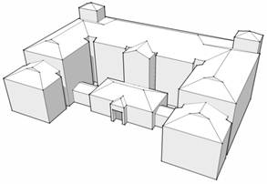
A similar massing which would be appropriate for Camp Lejeune.
Regarding windows, entrances, and details, BEQs shall adhere to the guidelines of the district in which they are located.
BEQ materials and colors shall be the following:
Colors BEQS
Description
|
Color
|
|
Facade
|
|
|
Building body
Screen walls
|
red flashed wire cut
standard grey mortar
|
|
Building body
Screen walls within French Creek
|

blended sand faced
standard grey mortar
|
|
Base foundation
|
white split face
white mortar
|
|
Painted Surfaces and Factory Finishes
|
|
Exterior stairs
Utilities/equipment
Appurtenances
|
slate gray
BM: 2133-40
PANTONE: 444
FED STD: 36173
|
|
Gutters/downspouts
Fascia/soffit/frieze
|
Match roof color
|
|
Handrails
|
clear anodized aluminum
|
|
Entry accents
Doors
|

taupe
HC-85
PANTONE:
FED STD:
|
|
|

brick red
2094-20
PANTONE
FED STD
|
|
|

tan
AC-33
PANTONE
FED STD
|
|
|

gray
HC-169
PANTONE
FED STD
|
|
Window/door trim
|
clear anodized aluminum
|
|
Roof Cladding
|
|
|
Metal roof
|
sandstone
BM: OC-48
PANTONE: 400
FED STD: 17875
|
|
|
taupe
HC-85
PANTONE:
FED STD:
|
|
|
slate gray
BM: 2133-40
PANTONE: 444
FED STD: 36173
|
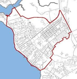
Hadnot Point’s Georgian and Colonial Revival style buildings are the dominant architectural precedent for much of Camp Lejeune, particularly for administrative facilities. Therefore, it is important that this area be preserved and future development respect the historic context.
Aside from Hadnot Point proper, this district is comprised of two sub-districts and an historic district: the Industrial Area, the Marine Corps Exchange Complex, and the Command Services/Regimental Area No. 3 historic district. Refer to Section 2.6 for more information on this historic district.
Massing
Building mass in this district shall be based on historical context, primarily the Georgian and Colonial Revival styles. Symmetry in building mass, windows, and roof shall be a large determinant of design.

Allowable roof forms are gable-on-hip and hip at slopes between 4:12 and 6:12.
Windows and Entrances
Windows and entrances shall be designed to match the historic character of Hadnot Point. Window dimensions shall fall within a range of 1:1.6 to 1:2 ratio of width to height, as shown in the diagram below. Windows shall have evenly spaced muntins dividing the glazing into 6, 8, or 12 equal parts to emphasize the historic look.

Window heads and sills shall be detailed to avoid a punched opening affect. This can be accomplished with different types of lintels which blend with the historic character, such as the jack arch or segmental arch. Sills may be precast concrete (preferred) or special brick shapes.

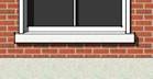
(Left) Example of jack arch using brick or precast concrete; (Right) Example of precast concrete sill
Entrances shall provide some type of weather protection, such as a pocketed door or canopy. Entrances must be formal, clearly identifiable and located toward the most common approach, preferably facing the public way or open space.
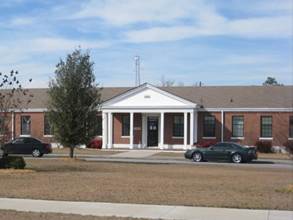
The primary entry element to Building 66 is covered, centrally located on a parking area, and faces on Holcomb Boulevard.
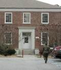
The side entry element to Building 2 is pocketed and clearly announced with a concrete cornice and surround.
Entry elements for the primary entrance shall be proportional to the building mass. In two story buildings, entry elements shall be greater than half the height of the building. In three and four story buildings, entry elements shall be at least two stories in height. In five story buildings, entry elements shall be at least three stories in height.
Entry elements shall be sized proportionately to building height
Body and Roof Materials
All facades in Hadnot Point shall be face brick, modular size. Base foundations shall be architectural concrete block.

Roofing shall be standing seam metal with high standing seams between 12 and 18 inches on center.

Composition shingles shall be laminated asphalt architectural shingles with a dimensional appearance.
Colors hadnot point
Description
|
Color
|
|
Facade
|
|
|
Building body
Screen walls
|
red flashed smooth
standard gray mortar
|
|
Base foundation
|
white split face
white mortar
|
|
Metal Panel
|
sandstone
BM: OC-48
PANTONE: 400
FED STD: 17875
|
|
Painted Surfaces and Factory Finishes
|
|
Exterior stairs
Utilities/equipment
Appurtenances
|
slate gray
BM: 2133-40
PANTONE: 444
FED STD: 36173
|
|
Gutters/downspouts
Fascia/soffit/frieze
|
taupe
HC-85
PANTONE:
FED STD:
|
|
|
bone white
BM: 2140-70
PANTONE: 9041
FED STD: 37875
|
|
Handrails
|
clear anodized aluminum
|
|
Entry accents
Doors
Window/door trim
|
bone white
BM: 2140-70
PANTONE: 9041
FED STD: 37875
|
|
Roof Cladding
|
|
|
Metal roof
|
taupe
HC-85
PANTONE:
FED STD:
|
|
Composition shingles
|

weathered wood
|
Details
Hadnot Point is known by its Georgian and Colonial Revival details. Exterior detail shall re-inforce this trend. Detail commonly associated with these styles includes:
· Brick quions
· Base foundations to water table line
· Molded cornices

Building 15 demonstrates details common to Hadnot Point: white base foundation, brick quoins, and embellished cornice
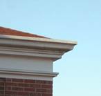
Molded cornice detail found in Georgian styles on Base
Proportion of the water table line and the height of the cornice detail to the overall building height shall be carefully controlled such that the respective dimensions of these elements are as follows:

The gable end on a gable-on-hip roof shall be equal in height to 1/3 of the overall roof height.
Precedents
Six building have been identified by Camp Lejeune as benchmarks for the character-defining elements associated with Hadnot Point, namely:
· Building 1, Base Headquarters
· Building 15, Medical Clinic
· Building 16, Chapel
· Building 17, Chapel
· Building 19, Theater
· Building 236, Training Pool
These structures are mostly two-story brick, with concrete or stone base foundations, sills, and lintels. The following buildings are equally valuable as precedents:
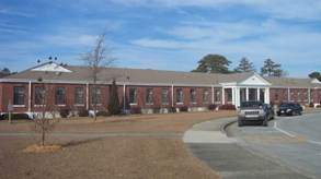
Building 66

Building 2
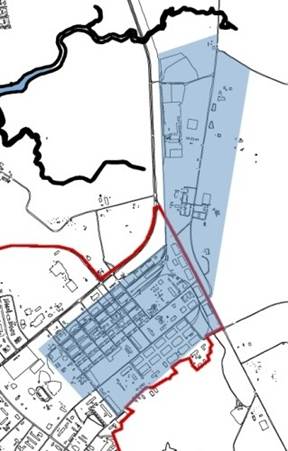
The industrial area is a sub-district within Hadnot Point and spans from the Steam Plant adjacent to the main parade field, north along the rail road line. See shaded area in blue (above).
Massing
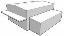
The industrial area requires special consideration. Building massing shall be inherently functional, but also preserve the scale of the district. Low shed roofs or overhangs are required to reduce the visual impact of large building volumes. Allowable roof forms are:
· low slope
· gable
· shed
· hip
Body and Roof Materials
Brick, concrete masonry, pre-cast concrete, and metal panel are acceptable materials in the Industrial sub-district. However the following restrictions apply:
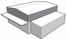
Metal panel shall be limited to 60 percent of the facade area.
Colors industrial area
Description
|
Color
|
|
Facade
|
|
|
Building body
Screen walls
|
red flashed smooth
standard gray mortar
|
|
Base Foundation for brick facade
|
white split face
white mortar
|
|
Concrete Masonry
|

cream matte face
mortar to match
|
|
Metal Panel
|
sandstone
BM: OC-48
PANTONE: 400
FED STD: 17875
|
|
Painted Surfaces and Factory Finishes
|
|
Exterior stairs
Utilities/equipment
Appurtenances
|
bone white
BM: 2140-70
PANTONE: 9041
FED STD: 37875
|
|
|
sandstone
BM: OC-48
PANTONE: 400
FED STD: 17875
|
|
Gutters/downspouts
Fascia/soffit/frieze
|
sandstone
BM: OC-48
PANTONE: 400
FED STD: 17875
|
|
|
bone white
BM: 2140-70
PANTONE: 9041
FED STD: 37875
|
|
Handrails
|
clear anodized aluminum
|
|
Entry accents
Doors
Window/door trim
|
bone white
BM: 2140-70
PANTONE: 9041
FED STD: 37875
|
|
|
clear anodized aluminum
|
|
Roof Cladding
|
|
|
Metal roof
|
sandstone
BM: OC-48
PANTONE: 400
FED STD: 17875
|
|
Composition shingles
|
weathered wood
|
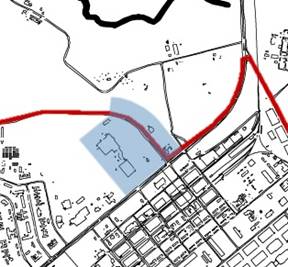
The Marine Corps Exchange Complex is a sub-district within Hadnot Point. It consists of MCCS services and private vendors surrounding the Marine Corps Exchange on Birch Road.
Massing
Due to the commercial nature of the Marine Corps Exchange Complex, designers must use massing which is both suitable to the character of Hadnot Point, but blend with the Exchange Mall.
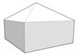
Roof forms are hip and square hip at slopes between 6:12 and 8:12.
Windows and Entrances
Windows and entrances shall adhere to the Hadnot Point details outlined above. In addition, entrances may use full height storefront systems, but only within the entry element and no where else along the facade.
Colors marine corps exchange
Description
|
Color
|
|
Facade
|
|
|
Building body
Screen walls
|
red flashed smooth
standard gray mortar
|
|
|
red flashed wire cut
standard gray mortar
|
|
Accent
|
white split face
white mortar
|
|
Metal Panel
|
sandstone
BM: OC-48
PANTONE: 400
FED STD: 17875
|
|
Painted Surfaces and Factory Finishes
|
|
Exterior stairs
Utilities/equipment
Appurtenances
|
bone white
BM: 2140-70
PANTONE: 9041
FED STD: 37875
|
|
Gutters/downspouts
Fascia/soffit/frieze
|
bone white
BM: 2140-70
PANTONE: 9041
FED STD: 37875
|
|
Handrails
|

medium bronze
BM: 2137-20
PANTONE: 405
FED STD: 33070
|
|
|
clear anodized aluminum
|
|
Entry accents
Doors
Window/door trim
|
medium bronze
BM: 2137-20
PANTONE: 405
FED STD: 33070
|
|
|
bone white
BM: 2140-70
PANTONE: 9041
FED STD: 37875
|
|
|
clear anodized aluminum
|
|
Roof Cladding
|
|
|
Metal roof
|

aged copper
|
|
Composition shingles
|
weathered wood
|
Precedents
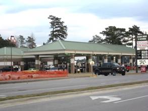
The Main Side C-Store
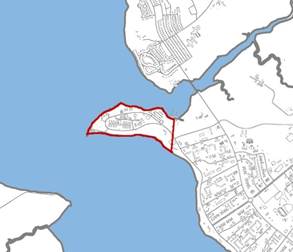
Hospital Point, similar to Hadnot Point, is predominantly historic Georgian style buildings. Building H-1, originally the Naval Hospital constructed in 1942, dominates this district in both architectural imageability and shear size of building. Structures are mostly two-story brick, with concrete or stone foundations, sills, and lintels.
Massing
Building massing in Hospital Point shall be based on historical context, primarily the Georgian and Colonial Revival styles. Symmetry in building mass, windows, and roof shall be a large determinant of design.
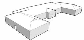
Allowable roof forms are gable-on-hip and hip at slopes between 4:12 and 6:12.
Windows and Entrances
Windows and entrances shall be designed to match the historic character of Hospital Point. Window dimensions shall fall within a range of 1:1.6 to 1:2 ratio of width to height, as shown in the diagram below. Windows shall have evenly spaced muntins dividing the glazing into 4, 6, or 8 parts to emphasize the historic look.

Window heads and sills shall be detailed to avoid a punched opening affect. This can be accomplished with different types of lintels which blend with the historic character, such as the jack arch or segmental arch. Sills may be precast concrete (preferred) or special brick shapes.


(Left) Example of jack arch using brick or precast concrete; (Right) Example of precast concrete sill
Entrances shall provide some type of weather protection, such as a pocketed door or canopy. Entrances must be formal, clearly identifiable and located toward the most common approach, preferably facing the public way or open space.
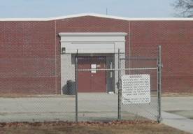
The primary entry to this armory is pocketed and embellished with a pre-cast concrete surround and entablature
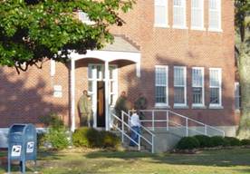
This secondary entry to a wing on Building H-1 is emphasized by surrounding glass and covered by a canopy

Entry elements for the primary entrance shall be proportional to the building mass. In two story buildings, entry elements shall be greater than half the height of the building. In three and four story buildings, entry elements shall be at least two stories in height. In five story buildings, entry elements shall be at least three stories in height.

Entry elements shall be sized proportionately to building height
Body and Roof Materials
All facades in Hospital Point shall be face brick, modular size. Base foundations shall be architectural concrete block.

Roofing shall be standing seam metal with high standing seams between 12 and 18 inches on center.

Composition shingles shall be laminated asphalt architectural shingles with a dimensional appearance.
Colors hospital point
Description
|
Color
|
|
Facade
|
|
|
Building body
Screen walls
|
red flashed smooth
standard gray mortar
|
|
Base Foundation
|
white split face
white mortar
|
|
Metal Panel
|
sandstone
BM: OC-48
PANTONE: 400
FED STD: 17875
|
|
Painted Surfaces and Factory Finishes
|
|
Exterior stairs
Utilities/equipment
Appurtenances
|
slate gray
BM: 2133-40
PANTONE: 444
FED STD: 36173
|
|
Gutters/downspouts
Fascia/soffit/frieze
|
bone white
BM: 2140-70
PANTONE: 9041
FED STD: 37875
|
|
Handrails
|
bone white
BM: 2140-70
PANTONE: 9041
FED STD: 37875
|
|
Entry accents
Doors
Window/door trim
|
bone white
BM: 2140-70
PANTONE: 9041
FED STD: 37875
|
|
Roof Cladding
|
|
|
Metal roof
|
taupe
HC-85
PANTONE:
FED STD:
|
|
Composition shingles
|
weathered wood
|
Details
Hospital Point is known by its Georgian style. Exterior detail shall re-inforce this trend. Detail commonly associated with these styles includes:
· Base foundations
· Molded cornices
· Semi or full round windows

Round window in the pediment of Building H-1
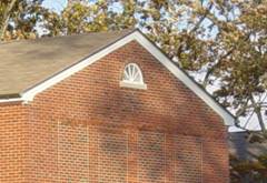
Semi-round window in the gable of a wing in Building H-1
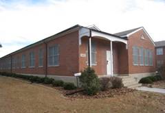
Base foundations such as on this building in Hospital Point are a key detail to the character of the district.
Proportion of the water table line and the height of the cornice detail to the overall building height shall be carefully controlled such that the respective dimensions of these elements are as follows:

The gable end on a gable-on-hip roof shall be equal in height to 1/3 of the overall roof height.
Precedents
Seven building have been identified by Camp Lejeune as building which contribute to the character of Hospital Point:
· Building H-1, HQ II MEF
· Building H-25, Officer's Quarters
· Building H-26, Officer's Quarters
· Building H-27, Officer's Quarters
· Building H-35, Utility Building
· Building H-41, Garage
· Building H-42, Garage
Of these, Building H-1 is the most important in defining the district and represents the best architectural characteristics.
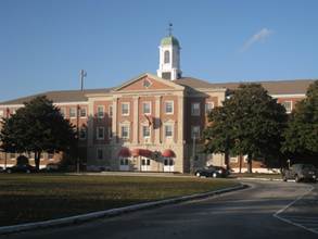
Building H-1
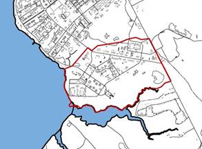
The majority of French Creek was developed in the late 1970s through to the late 1990s, and as a result, is typified by contemporary styles.
massing
Contemporary massing, rather than traditional historic massing, is required for the French Creek district. Buildings shall be designed to respond to the site, such that the building form fits contextually with surrounding forms whether they are other buildings, structures, or natural elements.
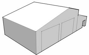
Allowable roof forms are the gable, the hip, and shed. Roofs shall be sloped from 4:12 to 6:12 pitch.
Eave overhangs shall extend at least 18" beyond face of wall, not including gutter, with fascia and soffits finished straight, not plumb.

Appropriate roof form for French Creek
windows and entrances
Windows shall have detail around heads and sills to avoid a "punched" opening effect. This may include precast concrete shapes, special brick shapes or brick detailing used as lintels and sills of the window opening. Window muntins are not preferred in French Creek except where necessary to support glazing or window operation.
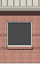
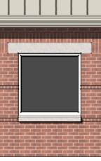
(Left) Window framed by a brick sill and soldier coursing above; (Right) window with pre-cast concrete lintel and sill
There are many acceptable entry elements for French Creek. The basic requirement is that primary building entrances be recognizable as obvious points of entry to the facility. At a minimum, this shall include overhead cover to shelter occupants from the weather and a storefront door and side light.
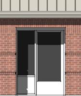
This represents the minimum requirement for an entry element in French Creek. In this case, overhead cover is provided by a pocketed entry.
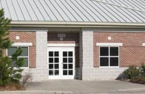
The entry element to Building FC-356 is fully glazed and protected from the weather. This entry also is facing the parking and public way.
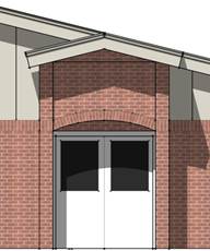
This entry is a double door with glazing and is protected by entry enclosure
Body and Roof Materials
All facades in French Creek shall be face brick, preferably modular size. Base foundations shall be architectural concrete block.

Roofing shall be standing seam metal with high standing seams between 12 and 18 inches on center.
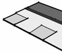
Composition shingles shall be laminated asphalt architectural shingles with a dimensional appearance.
Colors french creek
Description
|
Color
|
|
Facade
|
|
|
Building body
Screen walls
|
blended sand faced
standard gray mortar
|
|
|
red flashed smooth
standard gray mortar
|
|
|
red flashed wire cut
standard gray mortar
|
|
Base Foundation
|
white split face
white mortar
|
|
Metal Panel
|
sandstone
BM: OC-48
PANTONE: 400
FED STD: 17875
|
|
Painted Surfaces and Factory Finishes
|
|
Exterior stairs
Utilities/equipment
Appurtenances
|
slate gray
BM: 2133-40
PANTONE: 444
FED STD: 36173
|
|
Gutters/downspouts
Fascia/soffit/frieze
|
sandstone
BM: OC-48
PANTONE: 400
FED STD: 17875
|
|
|
bone white
BM: 2140-70
PANTONE: 9041
FED STD: 37875
|
|
Handrails
|
bone white
BM: 2140-70
PANTONE: 9041
FED STD: 37875
|
|
|
clear anodized aluminum
|
|
Entry accents
Doors
Window/door trim
|
bone white
BM: 2140-70
PANTONE: 9041
FED STD: 37875
|
|
|
clear anodized aluminum
|
|
Roof Cladding
|
|
|
Metal roof
|
sandstone
BM: OC-48
PANTONE: 400
FED STD: 17875
|
|
Composition shingles
|
weathered wood
|
Determining brick color
It may be difficult to determine the most appropriate brick color in the French Creek district due to the variety of existing shades. The default brick color shall always be the blended sand faced. However, the designer must conduct a site analysis to verify this as the most appropriate choice. Use the following steps:
1. Identify the project site and the surrounding significant structures. A rule of thumb: structures within 450 feet of the project site or any structure which has a large visual impact on the project site is significant.
2. Determine the brick colors of the surrounding structures. For the purpose of the study, brick shall be classified as either a brown or a red hue.
3. If the majority of the brick in surrounding significant buildings is a red hue, select the red brick from color chart. Otherwise use the default color.
4. If the project is an addition or replacement within a well-defined group or complex, such as a quad of BEQs, use the brick color associated with the existing structure or structures within the group.
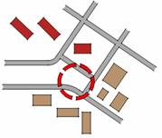
Example: The majority of surrounding significant buildings for the above project site is brown brick. Therefore the appropriate brick color should be brown to match the predominant context.
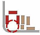
Example: The above project is completing a group of four BEQs, all of which are red. Therefore, the brick color should be red to complete the group.
Details
Details in French Creek primarily revolve around creative use of clay masonry units. Brick details and special brick shapes shall be used to give facades visual interest, to include:
· Common bond
· Soldier coursing
· Rowlock coursing
· Brick reveal
· Cove or bullnose water table
Common Bond

Soldier and Rowlock coursing, Brick reveal
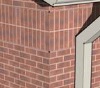
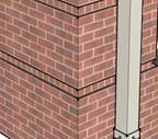
Combination of details

White base foundations are permitted. They shall of pre-cast concrete, smooth face concrete masonry units, or cast-in-place concrete with a high quality rubbed finish.
precedents
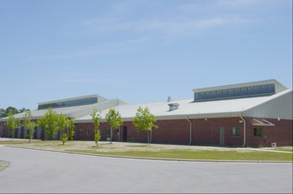
Building FC-230, maintenance facility
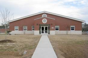
FC-292, administration facility
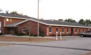
FC-294, fire station
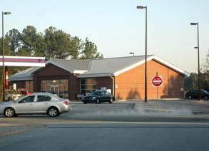
FC-298, gas station
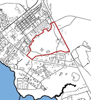
The Cogdels Creek District is located between Hadnot Point and French Creek. This area is recently developed and the architectural style is derived from the Georgian buildings in adjacent Hadnot Point. This area will be transformed by proposed bachelor housing construction and extension of Gonzales Boulevard through to Sneads Ferry Road. Birch Road is to be extended southward to the new Gonzales Boulevard connector.
Massing
Building mass in this district shall be based on the historical context of Hadnot Point, primarily the Georgian and Colonial Revival styles. Symmetry in building mass, windows, and roof shall be a large determinant of design.
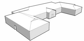
Allowable roof forms are gable-on-hip and hip at slopes between 4:12 and 6:12.
Windows and Entrances
Windows and entrances shall be designed to match the historic character seen in Georgian and Colonial Revival buildings throughout Camp Lejeune. Window dimensions shall fall within a range of 1:1.6 to 1:2 ratio of width to height, as shown in the diagram below. Windows shall have evenly spaced muntins dividing the glazing into 6, 8, or 12 equal parts to emphasize the historic look.

Window heads and sills shall be detailed to avoid a punched opening affect. This can be accomplished with different types of lintels which blend with the historic character, such as the jack arch or segmental arch. Sills may be precast concrete (preferred) or special brick shapes.

(Left) Example of jack arch using brick or precast concrete; (Right) Example of precast concrete sill
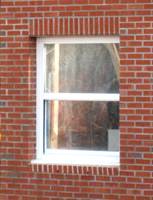
This is an alternate method of detailing around windows at Cogdels Creek
Entry elements for the primary entrance shall be proportional to the building mass. In two story buildings, entry elements shall be greater than half the height of the building. In three and four story buildings, entry elements shall be at least two stories in height. In five story buildings, entry elements shall be at least three stories in height.

Entry elements shaded for three and five story buildings

Entrances shall provide some type of weather protection, such as a pocketed door or canopy. Entrances must be formal, clearly identifiable and located toward the most common approach, preferably facing the public way or open space.
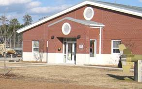
This facility located in French Creek demonstrates an entrance suitable for Cogdels Creek
Body and Roof Materials
All facades in Cogdels Creek shall be face brick, modular size. Base foundations shall be architectural concrete block.

Roofing shall be standing seam metal with high standing seams between 12 and 18 inches on center.
Colors cogdels creek
Description
|
Color
|
|
Facade
|
|
|
Building body
Screen walls
|
red flashed wire cut
standard gray mortar
|
|
Base Foundation
|
white split face
white mortar
|
|
Metal Panel
|
sandstone
BM: OC-48
PANTONE: 400
FED STD: 17875
|
|
Painted Surfaces
|
|
|
Exterior stairs
Utilities/equipment
Appurtenances
|
slate gray
BM: 2133-40
PANTONE: 444
FED STD: 36173
|
|
Gutters/downspouts
Fascia/soffit/frieze
|
bone white
BM: 2140-70
PANTONE: 9041
FED STD: 37875
|
|
|
sandstone
BM: OC-48
PANTONE: 400
FED STD: 17875
|
|
Handrails
|
bone white
BM: 2140-70
PANTONE: 9041
FED STD: 37875
|
|
|
clear anodized aluminum
|
|
Entry accents
Doors
Window/door trim
|
bone white
BM: 2140-70
PANTONE: 9041
FED STD: 37875
|
|
|
clear anodized aluminum
|
|
Roof Cladding
|
|
|
Metal roof
|
sandstone
BM: OC-48
PANTONE: 400
FED STD: 17875
|
Details
Cogdels Creek is characterized by Georgian and Colonial Revival styles. Exterior detail shall re-inforce this aesthetic, which includes, among others, the following:
· Base foundation
· Molded cornices
· Precast spandrel panels

Base foundation stops at a water table line. This may or may not align with the window sill, depending on window height and position.
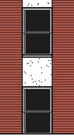
A pre-cast concrete spandrel panel in a contrasting color as a possible detail. This element can be seen on Building 1 in Hadnot Point.

Multi-level masses shall maintain the proportions of the classically-inspired styles. The above BEQ façade demonstrates adherence to historical proportions of the podium or base, which is established by white masonry, to the remainder of the façade. Single story masses shall be equally proportional:

The gable end on a gable-on-hip roof shall be equal in height to 1/3 of the overall roof height.
precedents
The Military Police Complex, including Buildings FC-1, FC-2, and FC-3 are precedents for future development in Cogdels Creek.
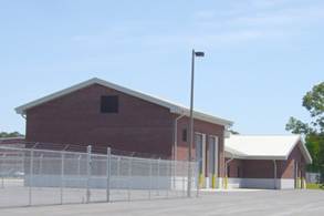
Military Police Maintenance Facility, Building FC-2
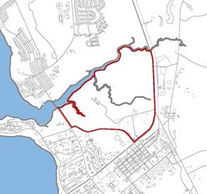
Wallace Creek experienced rapid development within a few years. Prior to this, the area consisted of a few small historical buildings and a contemporary complex of small brick single-story facilities. The architectural style of the newer development is derived from the Georgian buildings in adjacent Hadnot Point.
Massing
Building mass in this district shall be based on the historical context of Hadnot Point, primarily the Georgian and Colonial Revival styles. Symmetry in building mass, windows, and roof shall be a large determinant of design.

Allowable roof forms are gable-on-hip and hip at slopes between 4:12 and 6:12.
Windows and Entrances
Windows and entrances shall be designed to match the historic character seen in Georgian and Colonial Revival buildings throughout Camp Lejeune. Window dimensions shall fall within a range of 1:1.6 to 1:2 ratio of width to height, as shown in the diagram below. Windows shall have evenly spaced muntins dividing the glazing into 6, 8, or 12 equal parts to emphasize the historic look.
Window heads and sills shall be detailed to avoid a punched opening affect. This can be accomplished with different types of lintels which blend with the historic character, such as the jack arch or segmental arch. Sills may be precast concrete (preferred) or special brick shapes.


(Left) Example of jack arch using brick or precast concrete; (Right) Example of precast concrete sill

This is an alternate method of detailing around windows at Wallace Creek
Entry elements for the primary entrance shall be proportional to the building mass. In two story buildings, entry elements shall be greater than half the height of the building. In three and four story buildings, entry elements shall be at least two stories in height. In five story buildings, entry elements shall be at least three stories in height.
Entry elements shaded for three and five story buildings

Entrances shall provide some type of weather protection, such as a pocketed door or canopy. Entrances must be formal, clearly identifiable and located toward the most common approach, preferably facing the public way or open space.
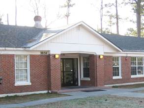
Entrance suitable for Wallace Creek
Body and Roof Materials
All facades in Wallace Creek shall be face brick, preferably modular size. Base foundations shall be architectural concrete block.

Roofing shall be standing seam metal with high standing seams between 12 and 18 inches on center.
Colors wallace creek
Description
|
Color
|
|
Facade
|
|
|
Building body
Screen walls
|
red flashed wire cut
standard gray mortar
|
|
Base Foundation
|
white split face
white mortar
|
|
Metal Panel
|
sandstone
BM: OC-48
PANTONE: 400
FED STD: 17875
|
|
Painted Surfaces and Factory Finishes
|
|
Exterior stairs
Utilities/equipment
Appurtenances
|
slate gray
BM: 2133-40
PANTONE: 444
FED STD: 36173
|
|
Gutters/downspouts
Fascia/soffit/frieze
|
bone white
BM: 2140-70
PANTONE: 9041
FED STD: 37875
|
|
Handrails
|
slate gray
BM: 2133-40
PANTONE: 444
FED STD: 36173
|
|
|
clear anodized aluminum
|
|
Entry accents
Doors
Window/door trim
|
bone white
BM: 2140-70
PANTONE: 9041
FED STD: 37875
|
|
Roof Cladding
|
|
|
Metal roof
|
sandstone
BM: OC-48
PANTONE: 400
FED STD: 17875
|
Details
Wallace Creek is characterized by Georgian and Colonial Revival details. Exterior detail shall re-inforce this trend and elements to do shall include:
· Base foundation to a water table line
· Molded cornices
· Precast spandrel panel
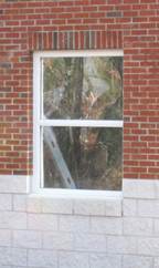
Base foundation stops at a water table line. This may or may not align with the window sill, depending on window requirements.
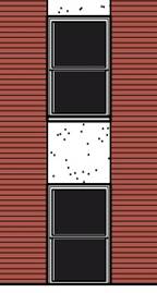
A pre-cast concrete spandrel panel in a contrasting color as a possible detail. This element can be seen on Building 1 in Hadnot Point.

Multi-level masses shall maintain the proportions of the classically-inspired styles. The above BEQ façade demonstrates adherence to historical proportions of the podium or base, which is established by white masonry, to the remainder of the façade. Single story masses shall be equally proportional:

The gable end on a gable-on-hip roof shall be equal in height to 1/3 of the overall roof height.
precedents
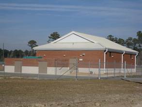
Telephone exchange building in Wallace Creek
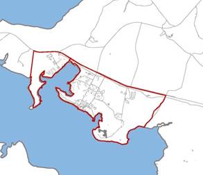
Courthouse Bay is characterized by single-story brick structures designed after the Georgian or Federalist styles. On newer buildings, these styles have been abstracted or exaggerated. The resultant character is a cohesive mix of old and new construction.
massing
Buildings in Courthouse Bay shall be respectful of the district’s historic character. However a strict adherence to a set of stylistic rules in not necessarily required. Massing shall be largely symmetrical with contemporary interpretations of the Georgian and Colonial Revival styles.

Allowable roof forms include the gable, gable-on-hip, and hip at slopes between 4:12 and 6:12.
windows and entrances
Windows and entrances shall be designed to match the historic character of Courthouse Bay. Windows shall have evenly spaced muntins dividing the glazing into 4, 6, or 8 parts to emphasize the historic look.
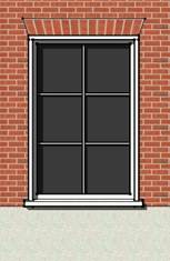
Window heads and sills shall be detailed to avoid a punched opening affect. This can be accomplished with different types of lintels which blend with the historic character, such as the jack arch or pre-cast concrete. Sills may be precast concrete (preferred) or special brick shapes.
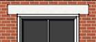

Entrances shall provide some type of weather protection, such as a pocketed door or canopy. Entrances must be formal, clearly identifiable and located toward the most common approach, preferably facing the public way or open space.
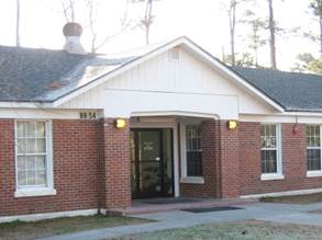
The MCCS Military Clothing Facility has a covered entrance announced with a gable end
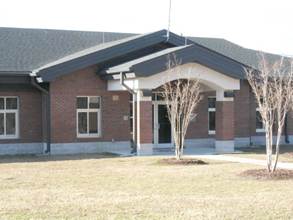
The covered entryway of the Joint Maritime Academic Facility
Body and Roof Materials
All facades in Hadnot Point shall be face brick, preferably modular size. Base foundations shall be architectural concrete block.
Roofing shall be standing seam metal with high standing seams between 12 and 18 inches on center.

Composition shingles shall be laminated asphalt architectural shingles with a dimensional appearance.
Colors courthouse bay
Description
|
Color
|
|
Facade
|
|
|
Building body
Screen walls
|
red flashed smooth
standard gray mortar
|
|
|
red flashed wire cut
standard gray mortar
|
|
Base Foundation
|
white split face
white mortar
|
|
Metal Panel
|
sandstone
BM: OC-48
PANTONE: 400
FED STD: 17875
|
|
Painted Surfaces and Factory Finishes
|
|
Exterior stairs
Utilities/equipment
Appurtenances
|
slate gray
BM: 2133-40
PANTONE: 444
FED STD: 36173
|
|
Gutters/downspouts
Fascia/soffit/frieze
|
bone white
BM: 2140-70
PANTONE: 9041
FED STD: 37875
|
|
|
sandstone
BM: OC-48
PANTONE: 400
FED STD: 17875
|
|
|
slate gray
BM: 2133-40
PANTONE: 444
FED STD: 36173
|
|
Handrails
|
clear anodized aluminum
|
|
Entry accents
Doors
Window/door trim
|
bone white
BM: 2140-70
PANTONE: 9041
FED STD: 37875
|
|
|
clear anodized aluminum
|
|
Roof Cladding
|
|
|
Metal roof
|
sandstone
BM: OC-48
PANTONE: 400
FED STD: 17875
|
|
|
slate gray
BM: 2133-40
PANTONE: 444
FED STD: 36173
|
|
Composition shingles
|
slate gray
|
Details
Courthouse Bay shares many details with Hadnot Point and Hospital Point, such as base foundations and molded cornices. But the district also owes much of its character to roof details such as:
· Dormers (gable fronted and eyebrow)
· Gable-on-hip
· Monitor
· Gable and monitor
· Clarestory windows
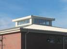
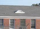
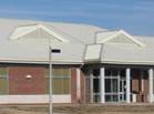
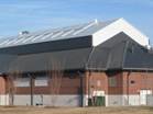
These roof details above enrich the visual impression of Courthouse Bay and shall be incorporated into design. From top left to bottom right: monitor, eyebrow, dormer with gable end, gable and monitor.
Precedents
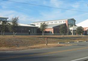
The fitness center, Building BB2
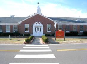
Engineer School Headquarters
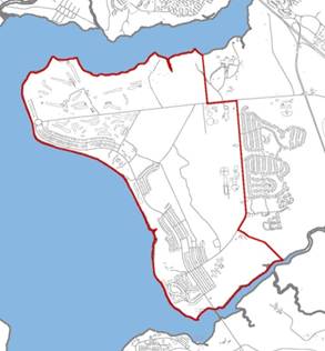
Paradise Point is the natural continuation of Hadnot and Hospital Point in regard to architectural style. However, its residential district and concentration of educational facilities gives Paradise Point a unique quality.
The significant character of Paradise Point is defined along Seth Williams Road, specifically from Marston Pavilion, the Officers Club, and the bachelor and visiting officers’ quarters. These buildings embody the Georgian styles seen elsewhere on Base.
Along Brewster Road, the district takes on a more residential appearance, particularly from the vernacular housing areas, the golf course club house, and the schools.
massing
Building mass in this district shall be based on historical context, primarily the Georgian and Colonial Revival styles. Symmetry in building mass, windows, and roof shall be a large determinant of design.

Allowable roof forms are gable-on-hip and hip at slopes between 4:12 and 6:12.
Windows and Entrances
Windows and entrances shall be designed to match the historic character of Paradise Point. Window dimensions shall fall within a range of 1:1.6 to 1:2 ratio of width to height, as shown in the diagram below. Windows shall have evenly spaced muntins dividing the glazing into 6, 8, or 12 equal parts to emphasize the historic look.
Window heads and sills shall be detailed to avoid a punched opening affect. This can be accomplished with different types of lintels which blend with the historic character, such as the jack arch or segmental arch. Sills may be precast concrete (preferred) or special brick shapes.

(Left) Example of jack arch using brick or precast concrete; (Right) Example of precast concrete sill
Entrances shall provide some type of weather protection, such as a pocketed door or canopy. Entrances must be formal, clearly identifiable and located toward the most common approach, preferably facing the public way or open space.
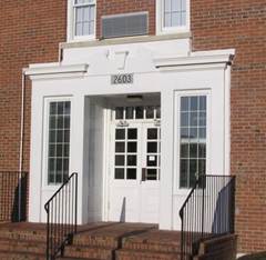
This entrance to the BOQ, Building 2603, is richly embellished with side lights, cornice detail, and a broken pediment
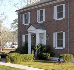
The entrance to Building 2601 is facing Seth Williams Road and is protected with a Colonial Revival style canopy
body and Roof Materials
All facades in Paradise Point shall be face brick, modular size. Base foundations may be architectural concrete block, pre-cast concrete, or cast-in-place concrete with a high quality rubbed finish.
Roofing shall be standing seam metal with high standing seams between 12 and 18 inches on center.
Composition shingles shall be laminated asphalt architectural shingles with a dimensional appearance.
Colors paradise point
Description
|
Color
|
|
Facade
|
|
|
Building body
Screen walls
|
red flashed smooth
standard gray mortar
|
|
Base Foundation
|
white split face
white mortar
|
|
Metal Panel
|
sandstone
BM: OC-48
PANTONE: 400
FED STD: 17875
|
|
Painted Surfaces and Factory Finishes
|
|
Exterior stairs
Utilities/equipment
Appurtenances
|
bone white
BM: 2140-70
PANTONE: 9041
FED STD: 37875
|
|
Gutters/downspouts
Fascia/soffit/frieze
|
bone white
BM: 2140-70
PANTONE: 9041
FED STD: 37875
|
|
Handrails
|
bone white
BM: 2140-70
PANTONE: 9041
FED STD: 37875
|
|
Entry accents
Doors
Window/door trim
|
bone white
BM: 2140-70
PANTONE: 9041
FED STD: 37875
|
|
Roof Cladding
|
|
|
Metal roof
|
taupe
HC-85
PANTONE:
FED STD:
|
|
Composition shingles
|
weathered wood
|
Details
Paradise Point is known by its Georgian and Colonial Revival details. Exterior detail shall re-inforce this trend by using the following:
· Brick quions
· Base foundations to a water table line
· Molded cornices
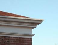
This molded cornice on Building 2615 Officers' Club (above) and the brick quoins (below) are examples of Georgian style details for Paradise Point.
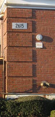
Proportion of the water table line and the height of the cornice detail to the overall building height shall be carefully controlled such that the respective dimensions of these elements are as follows:

The gable end on a gable-on-hip roof shall be equal in height to 1/3 of the overall roof height.
precedents
The significant character of Paradise Point is defined along Seth Williams Road, and specifically Marston Pavilion, the Officers Club, and the bachelor and visiting officers’ quarters. These buildings embody the Georgian styles seen elsewhere on Base.

The Officers’ Club
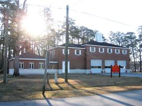
Fire station, Building 2600
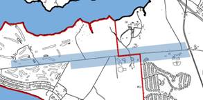
The Brewster Road area is a sub-district of Paradise Point and requires special consideration in design. This area is predominantly community buildings with a more informal contemporary character.
Massing
Due to the residential nature of Brewster Road, designers must use massing which is both suitable to the character of Paradise Point, but blend with the vernacular architecture of the neighborhoods.

Allowable roof forms are gable and hip at slopes between 4:12 and 6:12.
Windows and Entrances
Windows and entrances shall be designed to match the historic character of Paradise Point. Window dimensions shall fall within a range of 1:1.6 to 1:2 ratio of width to height, as shown in the diagram below. Windows shall have evenly spaced muntins dividing the glazing into 6, 8, or 12 equal parts to emphasize the historic look.

Window heads and sills shall be detailed to avoid a punched opening affect. This can be accomplished with different types of lintels such as the jack arch or soldier brick. Sills may be special brick shapes (preferred) or precast concrete. Shutters provide added emphasis to the window and contribute to the residential character.
Entrances shall provide some type of weather protection, such as a pocketed door or canopy. Entrances must be formal, clearly identifiable and located toward the most common approach, preferably facing the public way or open space.
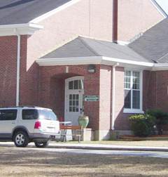
This entrance to Family Services Center, Building 40, is pocketed with an arched entry and transom window
body and Roof Materials
All facades in Paradise Point shall be face brick, modular size and base foundations architectural concrete block.

Roofing shall be standing seam metal with high standing seams between 12 and 18 inches on center.
Colors brewster road
Description
|
Color
|
|
Facade
|
|
|
Building body
Screen walls
|
red flashed smooth
standard gray mortar
|
|
Base Foundation
|
white split face
white mortar
|
|
Metal Panel
|
sandstone
BM: OC-48
PANTONE: 400
FED STD: 17875
|
|
Painted Surfaces and Factory Finishes
|
|
Exterior stairs
Utilities/equipment
Appurtenances
|
slate gray
BM: 2133-40
PANTONE: 444
FED STD: 36173
|
|
Gutters/downspouts
Fascia/soffit/frieze
|
sandstone
BM: OC-48
PANTONE: 400
FED STD: 17875
|
|
|
medium bronze
BM: 2137-20
PANTONE: 405
FED STD: 33070
|
|
|
bone white
BM: 2140-70
PANTONE: 9041
FED STD: 37875
|
|
Handrails
|
bone white
BM: 2140-70
PANTONE: 9041
FED STD: 37875
|
|
|
clear anodized aluminum
|
|
Entry accents
Doors
Window/door trim
|
bone white
BM: 2140-70
PANTONE: 9041
FED STD: 37875
|
|
Roof Cladding
|
|
|
Metal roof
|
sandstone
BM: OC-48
PANTONE: 400
FED STD: 17875
|
|
|
medium bronze
BM: 2137-20
PANTONE: 405
FED STD: 33070
|
Details
Brewster Road is predominantly community buildings surrounded by residential neighborhoods and detail shall emphasize this public space and welcoming character. For example:
· Colonnades
· Shutters
Colonnades on community buildings such as Lejeune High School and the Golf Course Club House face the public way, define the entrances, and are easy to enter.
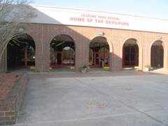

Massing
Massing in the Wounded Warrior Complex shall be largely symmetrical with formal entry elements.

Allowable roof forms are gable-on-hip and hip at slopes between 4:12 and 6:12.
Windows and Entrances
Windows shall have detail around heads and sills to avoid a "punched" opening effect. This may include precast concrete shapes, special brick shapes or brick detailing used as lintels and sills of the window opening. Window muntins are not preferred in the Wounded Warrior Complex except where necessary to support glazing or window operation.
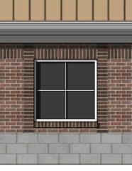
Entrances shall provide some type of weather protection, such as a pocketed door or canopy. Entrances must be formal, clearly identifiable and located toward the most common approach, preferably facing the public way or open space.
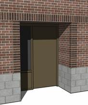
Single door pocketed entrance
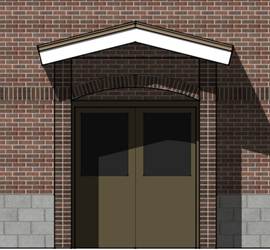
Double door entrance with canopy
body and Roof Materials
All facades in Wounded Warrior Complex shall be face brick. Base foundations shall be architectural concrete block.
Roofing shall be standing seam metal with high standing seams between 12 and 18 inches on center.
COLORS WOUNDED WARRIOR COMPLEX
Description
|
Color
|
|
Facade
|
|
|
Building body
Screen walls
|

blended flashed wire cut
standard gray mortar
|
|
Base Foundation
|
gray split face
standard gray mortar
|
|
Metal Panel
|
sandstone
BM: OC-48
PANTONE: 400
FED STD: 17875
|
|
Painted Surfaces and Factory Finishes
|
|
Exterior stairs
Utilities/equipment
Appurtenances
|
slate gray
BM: 2133-40
PANTONE: 444
FED STD: 36173
|
|
Gutters/downspouts
Fascia/soffit/frieze
|
bone white
BM: 2140-70
PANTONE: 9041
FED STD: 37875
|
|
Handrails
Entry accents
|
bone white
BM: 2140-70
PANTONE: 9041
FED STD: 37875
|
|
|
clear anodized aluminum
|
|
Doors and door trim
|
medium bronze
BM: 2137-20
PANTONE: 405
FED STD: 33070
|
|
Window trim
|
bone white
BM: 2140-70
PANTONE: 9041
FED STD: 37875
|
|
Roof Cladding
|
|
|
Metal roof
|

tan
BM: HC-77
PANTONE:
FED STD:
|
Details
Two predominant details separate Wounded Warrior Complex from the surrounding area in Paradise Point:
· Brick accent bands
· Round louver
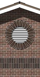
Round bricked louver in the gable end; accent band is located at the eave line
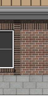
Dark accent bands along window jambs and heads break up the façade and create visual interest; these may be combined with a reveal for an added shadow line
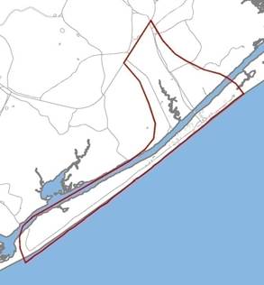
The Onslow Beach district is located on the North Carolina ocean front and as such, provides unique recreational opportunity to the Base. Its development has been primarily toward that goal, although there is a small training area on the south end of the district.
massing
Onslow Beach is a mix of beach houses, residential vernacular and utilitarian buildings, but is dominated by the Shingle style. Massing is also influenced by the beach environment and compliance with coastal area environmental regulations.
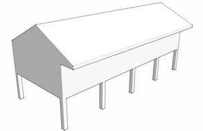
The Coastal Area Management Act of North Carolina and coastal construction standards regulate development at Onslow Beach. These guidelines must be followed, but in general they contribute positively to the character of the district and protect the environment for the future recreational use of Camp Lejeune. The most obvious affect on appearance is the requirement to raise structures above grade to allow for shifting sand and minimize environmental impact.

Refer to the Coastal Area Management Act for specifics on construction standards at Onslow Beach
Allowable roof forms are the gable, hip, and shed roofs at slopes between 4:12 and 6:12.
Windows and entrances
Windows and entrances shall be designed to match the existing Shingle style buildings at Onslow Beach. Windows should be either casement or sash types, and grouped in two's and three's. Window glazing shall be divided into small, multiple lights.
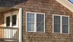
The windows on Building BA-95, Senior NCO Recreation Pavilion, are grouped in two's, consistent with the Shingle style
Entrances do no require the formality of many other districts, but shall be protected in some manner, either by locating under a porch roof or a separate canopy.
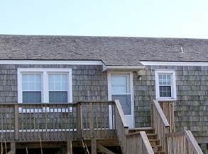
This Officers' Beach House, BA-146, has a covered entry door.
Body and roof materials
Facades on recreational facilities in Onslow Beach shall be cementitious siding. Siding shall shingle style, pre-finished, random pattern, with a straight edge and 5 to 6 inch exposure.

Roofing shall be either cedar shake or composition shingles.
Composition shingles shall be laminated asphalt architectural shingles with a dimensional appearance.
colors onslow beach
Description
|
Color
|
|
Facade
|
|
|
Building body
Screen walls
|

tan wood grain
|
|
Alternate color
|

gray wood grain
|
|
Metal Panel
|
sandstone
BM: OC-48
PANTONE: 400
FED STD: 17875
|
|
Painted Surfaces
|
|
|
Utilities/equipment
Appurtenances
|
bone white
BM: 2140-70
PANTONE: 9041
FED STD: 37875
|
|
Gutters/downspouts
Fascia/frieze
|
bone white
BM: 2140-70
PANTONE: 9041
FED STD: 37875
|
|
Exterior stairs
Handrails
Decking
|

treated wood
|
|
Entry accents
Doors
Window/door trim
|
bone white
BM: 2140-70
PANTONE: 9041
FED STD: 37875
|
|
Roof Cladding
|
|
|
Wood shingles
|

cedar
|
|
Composition shingles
|
slate
|
details
The existing buildings in this district have established character through elements common to the Shingle style. Details shall be incorporated in new structures to re-inforce this, including:
· Little or no roof overhangs
· Covered porches
· Expanses of shingles with little or no ornament
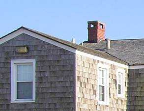
This General Officers' Beach House has virtually no roof overhang in order to showcase the shingled facade.
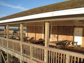
The Enlisted Beach Pavilion, BA-96, uses a covered porch for the outdoor seating area
precedents
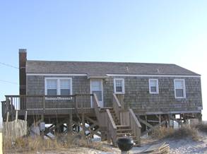
Building BA-146, Officers' Beach House
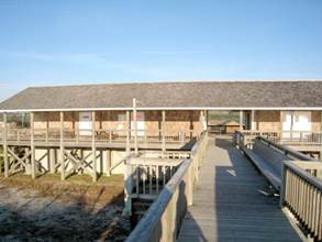
Building BA-95, Senior Enlisted Pavilion
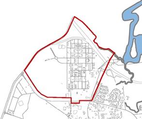
Camp Geiger is located adjacent to Marine Corps Air Station New River, but its primary tenant is the School of Infantry. As a result, the nature of this area and its design requirements differ from the neighboring air station.
massing

Allowable roof forms are gable, shed, mansard, and hip roofs at slopes from 4:12 to 6:12.
windows and entrances
Windows shall have detail around heads and sills to avoid a "punched" opening effect. This may include precast concrete shapes, special brick shapes or brick detailing at the lintel and sill elements of the window opening. Window muntins are not preferred in Camp Geiger except where necessary to support glazing or window operation.
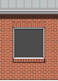
There are many acceptable entry elements for Camp Geiger. The basic requirement is that primary building entrances be recognizable as obvious points of entry to the facility. At a minimum, this shall include overhead cover to shelter occupants from the weather and a storefront door and side light.
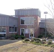
The entry element to fitness center, Building G-930, is easily recognizable
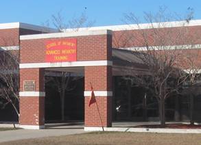
The entry element to academic facility Building G-615, is clearly called out and provides a covered space
Primary entrances shall be proportional to the building mass. Two story building entry elements shall be greater than half the height of the building. In three and four story buildings, entry elements shall be at least two stories in height. In five story buildings, entry elements shall be at least three stories in height.
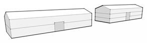
Entry elements shall be sized proportionately to building height
body and roof materials
All facades in Camp Geiger shall be face brick, preferably modular size, smooth faced architectural concrete block, or metal panel. Metal panels shall have a flat profile with panel widths of 36 inches or greater.

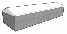
Metal panel has the following restrictions: limited to 10 percent of the facade area and confined to gable ends and adjacent to eaves.

Roofing shall be standing seam metal with high standing seams between 12 and 18 inches on center.

Asphalt shingles shall be laminated architectural shingles with a dimensional appearance.
Colors camp geiger
Description
|
Color
|
|
Facade
|
|
|
Building body
Screen walls
|
red flashed wire cut
standard gray mortar
|
|
Banding
|
white split face
white mortar
|
|
Metal Panel
|
sandstone
BM: OC-48
PANTONE: 400
FED STD: 17875
|
|
Painted Surfaces and Factory Finishes
|
|
Exterior stairs
Utilities/equipment
Appurtenances
|
slate gray
BM: 2133-40
PANTONE: 444
FED STD: 36173
|
|
Gutters/downspouts
Fascia/soffit/frieze
|
slate gray
BM: 2133-40
PANTONE: 444
FED STD: 36173
|
|
|
bone white
BM: 2140-70
PANTONE: 9041
FED STD: 37875
|
|
Handrails
|
clear anodized aluminum
|
|
Entry accents
Doors
Window and door trim
|
bone white
BM: 2140-70
PANTONE: 9041
FED STD: 37875
|
|
|
clear anodized aluminum
|
|
Roof Cladding
|
|
|
Prefinished metal roof
|
slate gray
BM: 2133-40
PANTONE: 444
FED STD: 36173
|
|
Composition shingles
|
slate gray
|
Details
Camp Geiger is an area of intense training activity for relatively new and young Marines, a particularly transient population. It is especially important to establish a sense of place that provides grounding for the experience of living and working at Camp Geiger.
Banding
The distinctive white banding on many buildings contributes to the theme of the district and evokes a sense of rhythm, order, and discipline.

Two bands on a single story building is enough to convey the intent but not over-do the detail.
precedents
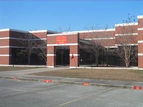
This academic instruction facility, Building G-615, is good example of many design elements at Camp Geiger.
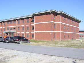
These open bay barracks, Building G-702, set a good precedent for multi-story design.
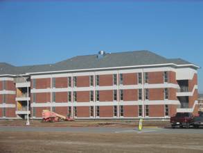
The horizontal banding on this BEQ, which is a structural element, sets the precedent for the distinctive detail on future buildings.
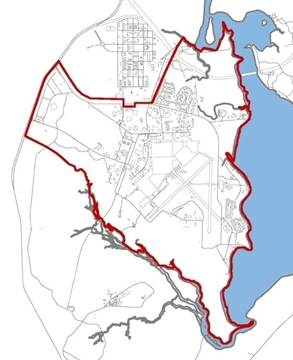
Marine Corps Air Station New River is largely an independent installation, but has a common history with Camp Lejeune and MCAS Cherry Point. It continues to share some support services with Camp Lejeune and is included in the BEAP as a separate district.
massing
There is a wide range of architecture at New River, as well as facility types that are unique to an airfield. The utilitarian theme of the airfield function should not influence other areas of the Installation. Two types of massings are required:
Administration and Support Buildings
These buildings include offices, conference spaces, command functions, batchelor housing, base support services and any structure not solely associated with the flight line. Massing of these buildings shall be clean, simple, and contemporary forms. Use submassing for larger structures to break up the building volume.
Allowable roof forms include the gable, shed, and hip roofs at slopes between 4:12 and 6:12.
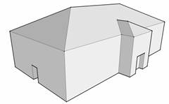
Airfield Facilities and Hangars
These buildings include facilities in the airfield area such as aircraft maintenance hangars, simulator buildings, and warehouses. Massing shall be largely functional, with exposed structure. Submassing to enclose ancillary functions helps reduce the monumental scale of these buildings.
Roofs shall be gable, hip, or shed at slopes greater than 2:12 (to reduce roof heat island effects) and less than 4:12.
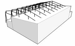
This massing diagram illustrates a hanger with a cantilevered truss roof
windows and entrances
Windows shall have detail around heads and sills to avoid a "punched" opening effect. This may include special brick shapes or brick detailing as lintel and sill elements of the window opening. Window muntins are not preferred in New River except where necessary to support glazing or window operation.
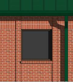
Window framed by brick pilasters and soldier coursing above
There are many acceptable entry elements for New River. The basic requirement is that primary building entrances be recognizable as obvious points of entry to the facility. At a minimum, this shall include overhead cover to shelter occupants from the weather and a storefront door and side light.
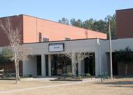
The entry element to the fitness center, Building AS-4000, is emphasized with contrasting color and covered by a canopy
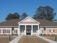
The entry to this community center is formally placed and faces the public open space and parking.
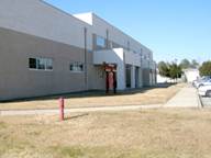
The entry to this operational trainer facility, AS-255, is facing the parking area and provides a covered area adjacent to the door.
body and roof materials
Administration, Support, and Airfield Facilities
These buildings shall be face brick, preferably modular size, smooth faced architectural concrete block, or metal panel. Alternate colors are permitted where building type and location warrant – see color chart. Metal panels shall have a flat profile with panel widths of 36 inches or greater.

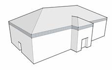
Metal panel has the following restrictions: limited to 10 percent of the facade area and confined to gable ends and adjacent to eaves.

Roofing shall be standing seam metal with high standing seams between 12 and 18 inches on center.

Asphalt shingles shall be laminated architectural shingles with a dimensional appearance.
Hangars
All hangers and other airfield district buildings in New River shall be face brick, modular size, smooth faced architectural concrete block, or metal panel. Metal panels shall have a flat profile with panel widths of 36 inches or greater.
Metal panel may consist of 100 percent of the facade.
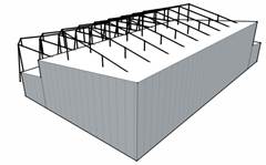
Roofing may be either standing seam metal or built-up roofing. Standing seam metal shall have high standing seams between 12 and 18 inches on center.
Built-up roofing shall have as high a solar reflectance as possible without affecting aircraft operations.
Colors new river
Description
|
Color
|
|
Facade
|
|
|
Building body
Screen walls
|
red flashed wire cut
standard gray mortar
|
|
Alternate building body
|

beige wire cut
standard gray mortar
|
|
|

white matte face
white mortar
|
|
Metal panel
|

almond
BM: OC-32
PANTONE: 9583
FED STD: 27722
|
|
|
sandstone
BM: OC-48
PANTONE: 400
FED STD: 17875
|
|
Painted Surfaces and Factory Finishes
|
|
Exterior stairs
Utilities/equipment
Appurtenances
|
slate gray
BM: 2133-40
PANTONE: 444
FED STD: 36173
|
|
Gutters/downspouts
Fascia/soffit/frieze
|
evergreen
BM: 2040-10
PANTONE: 7484
FED STD: 14109
|
|
|
slate gray
BM: 2133-40
PANTONE: 444
FED STD: 36173
|
|
Handrails
|
medium bronze
BM: 2137-20
PANTONE: 405
FED STD: 33070
|
|
|
clear anodized aluminum
|
|
Entry accents
Doors
Window/door trim
|
medium bronze
BM: 2137-20
PANTONE: 405
FED STD: 33070
|
|
|
evergreen
BM: 2040-10
PANTONE: 7484
FED STD: 14109
|
|
Roof Cladding
|
|
|
Metal roof
|
evergreen
BM: 2040-10
PANTONE: 7484
FED STD: 14109
|
|
Low slope roof
|
white
|
Airfield Buildings
Façade materials consist of a mixture of brick, block, stucco, and metal panel. Roofs range from low slope to high slope gable and gable on hip. Standing seam metal is the predominant cladding for sloped roofs, although there is some asphalt shingle. Common details include pilasters and gabled entryways, particularly on BEQs.
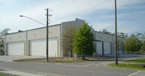
Building AS-265 with its translucent, vertically-acting hangar doors
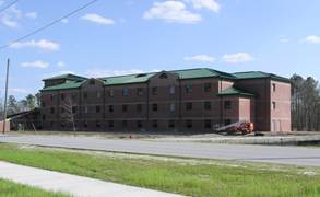
Conspicuous green pitched metal roof of recently-built BEQs
The following building is adjacent to other training bays and uses the alternate color palette.
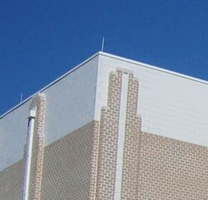
Pilaster details are prevalent on high bay buildings, usually aligned with scuppers and downspouts;
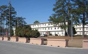
Barriers placed in front of the MAG 26 Headquarters
Anti-terrorism/Force Protection standoff should be achieved by use of more integrated and less conspicuous means such as bollards, ditches and berms, or anti-ramming knee walls incorporated into the site design and veneered with materials similar to adjacent buildings.
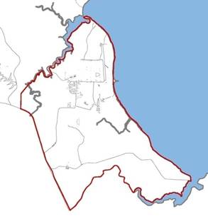
Stone Bay is located along the western banks of the New River and is relatively isolated from the remainder of the special districts. Generally, Stone Bay consists of archetypal Georgian buildings found on Camp Lejeune. However, due to the rapid construction of the Marine Special Operations Command (MARSOC) complex beginning in 2008, separate styles have developed. In addition to Stone Bay "proper", there are two distinct sub-districts: the MARSOC complex, consisting of contemporary brick and standing seam metal buildings, and the Rifle Range Historic Area, the original historic area adjacent to the rifle ranges. Refer to Section 2.6 for more information on this historic district.
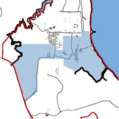
This section applies to all facilities along Rifle Range Road, Booker T. Washington Boulevard, and any structures that do not fall within the Rifle Range or MARSOC sub-districts. This represents the common support area for all activity at Stone Bay.
massing
Buildings in Stone Bay Common Support Area shall be respectful of the district’s historic character. However a strict adherence to a set of stylistic rules is not necessary. Massing shall be largely symmetrical with contemporary interpretations of the Georgian and Colonial Revival styles.
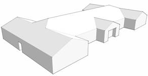
Allowable roof forms include the gable, gable-on-hip, and hip at slopes between 4:12 and 6:12.
windows and entrances
Windows shall have detail around heads and sills to avoid a "punched" opening effect. This may include precast concrete shapes, special brick shapes or brick detailing at the lintel and sill elements of the window opening. Window muntins are not required except where necessary to support glazing or window operation.
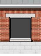
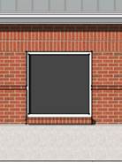
Entrances shall provide some type of weather protection, such as a pocketed door or canopy. Entrances must be formal, clearly identifiable and located toward the most common approach, preferably facing the public way or open space.
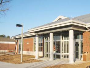
This entrance to the dining facility, building RR-135, is clearly announced, covered, and faces the public way
Body and Roof Materials
All facades in Stone Bay Common Support Area shall be face brick, modular size. Base foundations may be architectural concrete block, precast concrete, or cast-in-place concrete with a high quality rubbed finish.

Roofing shall be standing seam metal with high standing seams between 12 and 18 inches on center.
Colors stone bay
Description
|
Color
|
|
Facade
|
|
|
Building body
Screen walls
|
red flashed wire cut
standard gray mortar
|
|
Base foundation
|
white split face
white mortar
|
|
Metal Panel
|
sandstone
BM: OC-48
PANTONE: 400
FED STD: 17875
|
|
Painted Surfaces and Factory Finishes
|
|
Exterior stairs
Utilities/equipment
Appurtenances
|
slate gray
BM: 2133-40
PANTONE: 444
FED STD: 36173
|
|
Gutters/downspouts
Fascia/soffit/frieze
|

silver
|
|
|
bone white
BM: 2140-70
PANTONE: 9041
FED STD: 37875
|
|
Handrails
|
clear anodized aluminum
|
|
Entry accents
Doors
Window/door trim
|
bone white
BM: 2140-70
PANTONE: 9041
FED STD: 37875
|
|
|
clear anodized aluminum
|
|
Roof Cladding
|
|
|
Metal roof
|
silver
|
Details
Detail suitable for Stone Bay is both respectful of the nearby historic context and contemporary design. This includes the following:
· Dormers (gable fronted)
· Downspout accents
· Masonry base foundation

Gable fronted dormers on the roof of the dining facility, Building RR-135
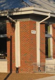
Architectural block accents this building corner; downspouts are aligned with these accents to create an orderly and modern detail
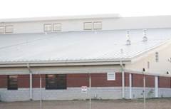
The base foundation of the Reserve Center buildings is architectural block
Precedents
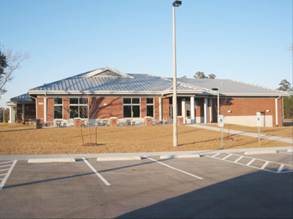
Dining Facility, RR-135
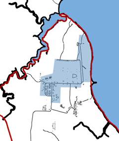
Massing
Building mass in the Rifle Range area shall be based on historical context, primarily the Georgian and Colonial Revival styles. Symmetry in building mass, windows, and roof shall be a large determinant of design.
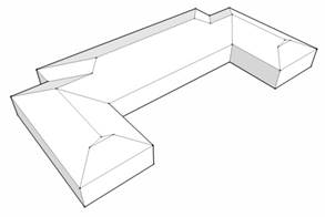
Allowable roof forms are gable-on-hip and hip at slopes between 4:12 and 6:12.
Proportion of the water table line and the height of the cornice detail to the overall building height shall be carefully controlled such that the respective dimensions of these elements are as follows:

The gable end on a gable-on-hip roof shall be equal in height to 1/3 of the overall roof height.
Windows and Entrances
Windows and entrances shall be designed to match the historic character of the Stone Bay Rifle Range area. Window dimensions shall fall within a range of 1:1.6 to 1:2 ratio of width to height, as shown in the diagram below. Windows shall have evenly spaced muntins dividing the glazing into 6, 8, or 12 equal parts to emphasize the historic look.

Window heads and sills shall be detailed to avoid a punched opening affect. This can be accomplished with different types of lintels which blend with the historic character, such as the jack arch or segmental arch. Sills may be precast concrete (preferred) or special brick shapes.
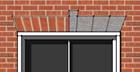
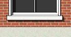
(Left) Example of jack arch using brick or precast concrete; (Right) Example of precast concrete sill
Entrances shall provide some type of weather protection, such as a pocketed door or canopy. Entrances must be formal, clearly identifiable and located toward the most common approach, preferably facing the public way or open space.
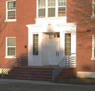
The primary entry element to Walsh Hall, Building RR-9, is framed by a glazed surround and cornice and faces on Rifle Range Road
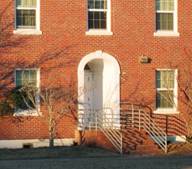
The side entry element to Building RR-9 is pocketed and clearly announced with an ornamental surround.
Primary entrances shall be proportional to the building mass. In three and four story buildings, entry elements shall be at least two stories in height. In five story buildings, entry elements shall be at least three stories in height.
Entry elements shall be sized proportionately to building height
Body and Roof Materials
All facades in Stone Bay Rifle Range area shall be face brick, preferably modular size. Base foundations shall be architectural concrete block.
Roofing shall be composition shingle consisting of laminated asphalt with a dimensional appearance.
Colors rifle range
Description
|
Color
|
|
Facade
|
|
|
Building body
Screen walls
|
red flashed smooth
standard gray mortar
|
|
Base Foundation
|
white split face
white mortar
|
|
Metal Panel
|
sandstone
BM: OC-48
PANTONE: 400
FED STD: 17875
|
|
Painted Surfaces and Factory Finishes
|
|
Exterior stairs
Utilities/equipment
Appurtenances
|
slate gray
BM: 2133-40
PANTONE: 444
FED STD: 36173
|
|
|
bone white
BM: 2140-70
PANTONE: 9041
FED STD: 37875
|
|
Gutters/downspouts
Fascia/soffit/frieze
|
slate gray
BM: 2133-40
PANTONE: 444
FED STD: 36173
|
|
|
bone white
BM: 2140-70
PANTONE: 9041
FED STD: 37875
|
|
Handrails
|
slate gray
BM: 2133-40
PANTONE: 444
FED STD: 36173
|
|
|
bone white
BM: 2140-70
PANTONE: 9041
FED STD: 37875
|
|
Entry accents
Doors
Window/door trim
|
bone white
BM: 2140-70
PANTONE: 9041
FED STD: 37875
|
|
Roof Cladding
|
|
|
Composition shingles
|
weathered wood
|
Details
This area is known by its Georgian and Colonial Revival details. Exterior detail shall re-inforce this trend. Detail commonly associated with these styles includes:
· Brick quiones
· Raised concrete foundations
· Moulded cornice detail
· Brick common bond

This gymnasium, Building RR-8, has many elements associated with the character of this area.

Precedents
There are numerous historic buildings identified by Camp Lejeune as contributing to the character-defining elements associated with Stone Bay Rifle Range area, particularly the dining facility and surrounding barracks. The following are appropriate to use as design precedents:
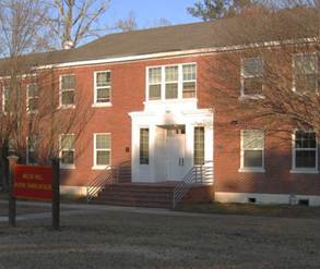
Walsh Hall is typical example of the historic Georgian style that exists in the original Rifle Range area.
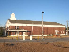
The gymnasium, Building RR-8, is a good precedent for its use of characteristic elements of the area
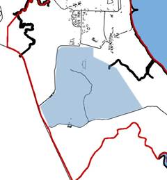
Massing
The MARSOC structures are more contemporary in massing and put less emphasis on classical rules of style.
 Many existing roofs in the MARSOC complex are mansards designed to appear as hip roofs. New roof forms shall be gable, mansard, or hip with slopes between 4:12 and 6:12.
windows and entrances
Windows shall have detail around heads and sills to avoid a "punched" opening effect. This may include precast concrete shapes, special brick shapes or brick detailing as lintel and sill elements of the window opening. Window muntins are not preferred in MARSOC except where necessary to support glazing or operable windows.
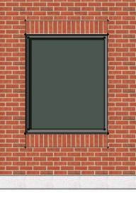
There are many acceptable entry elements for MARSOC. The basic requirement is that primary building entrances be recognizable as obvious points of entry to the facility. At a minimum, this shall include overhead cover to shelter occupants from the weather and a storefront door and side light.
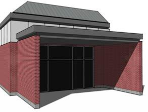
The entrance to this facility is sheltered by a canopy
Body and Roof Materials
All facades in the MARSOC area shall be face brick, preferably modular size. Base foundations may be architectural concrete block, precast concrete, or cast-in-place concrete with a high quality rubbed finish.

Roofing shall be standing seam metal with high standing seams between 12 and 18 inches on center.
Colors marsoc
Description
|
Color
|
|
Facade
|
|
|
Building body
Screen walls
|
red flashed wire cut
standard gray mortar
|
|
Base foundation
|

gray split face
standard gray mortar
|
|
Metal Panel
|
sandstone
BM: OC-48
PANTONE: 400
FED STD: 17875
|
|
Painted Surfaces and Factory Finishes
|
|
Exterior stairs
Utilities/equipment
Appurtenances
|
slate gray
BM: 2133-40
PANTONE: 444
FED STD: 36173
|
|
Gutters/downspouts
Fascia/soffit/frieze
|
slate gray
BM: 2133-40
PANTONE: 444
FED STD: 36173
|
|
Handrails
|
slate gray
BM: 2133-40
PANTONE: 444
FED STD: 36173
|
|
Entry accents
Doors
Window/door trim
|
slate gray
BM: 2133-40
PANTONE: 444
FED STD: 36173
|
|
Roof Cladding
|
|
|
Metal roof
|
slate gray
BM: 2133-40
PANTONE: 444
FED STD: 36173
|
details
Details of the MARSOC buildings are abstracted from the classical design style. The elements that shall be used on buildings in this area include:
· Single course block base foundation
· Recessed frieze detail at cornice
· Variety of brick detail including soldier coursing, reveals, and set backs

In order to maintain the character of MARSOC, the recessed frieze detail shall be duplicated on building cornices regardless of the method of wall and roof construction.

This diagram illustrates the recommended dimensions for the recessed frieze detail at the building cornice
precedents
The single most dominating building on the MARSOC complex is the headquarters building, which should be used as a precedent for the majority of design elements.
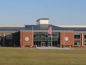
The MARSOC Headquarters building sets the theme for the rest of the MARSOC complex.
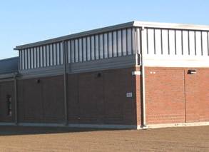
This MARSOC facility is another good precedent for elements characteristic to the MARSOC complex
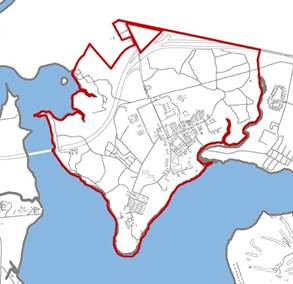
Camp Johnson experienced a large initial development in the 1940s and remained relatively unchanged for 40 years. In the mid 1980s, it began to see modest but steady development, mostly in the northern side of Montford Point.
The staggered pace of development has resulted in a fragmented character for the district. Historic structures are mostly single-story buildings with white or cream colored stucco facades, typically with simple gable roofs. Doors and windows are framed with exposed brick. Much of the original development is analogous to typologies seen at Hadnot Point.
Massing
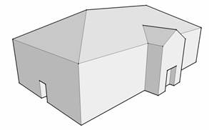
Proportion of the water table line and the height of the cornice detail to the overall building height shall be carefully controlled such that the respective dimensions of these elements are as follows:

Allowable roof forms are gable, shed, mansard, and hip roofs at slopes from 4:12 to 6:12.

Windows and entrances
Windows shall have detail around heads, sills, and jambs to avoid a "punched" opening effect. This may include special brick shapes, brick detailing at lintel and sill, or variations of material above or below the window element, such as a base foundation or recessed spandrel panel. Window muntins shall not exceed more than 4 divisions of a single window.
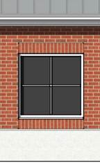
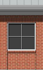
Two variations of acceptable window details for Camp Johnson; base foundation (left) and recessed panel below window (right)
Entrances shall provide some type of weather protection, such as a pocketed door or canopy. Entrances must be formal, clearly identifiable and located toward the most common approach, preferably facing the public way or open space.
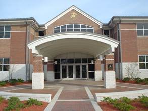
A building such as this instruction facility, Building M-79, has a formal entry element with hardscape and canopy to announce its presence
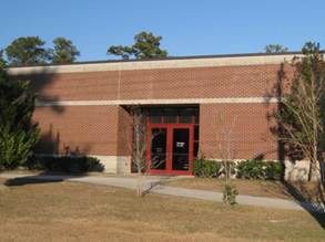
The entry element to this indoor gym, Building M-168 is framed by glazed storefront and pocketed for weather protection
Body and roof materials
All facades in Camp Johnson shall be face brick, preferably modular size. Base foundations may be architectural concrete block, precast concrete, or cast-in-place concrete with a high quality rubbed finish.

Roofing shall be standing seam metal with high standing seams between 12 and 18 inches on center.
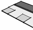
Asphalt shingles shall be laminated architectural shingles with a dimensional appearance.
Colors camp Johnson
Description
|
Color
|
|
Facade
|
|
|
Building body
Screen walls
|
red flashed wire cut
standard gray mortar
|
|
Base foundation
|
white split face
white mortar
|
|
Metal Panel
|
sandstone
BM: OC-48
PANTONE: 400
FED STD: 17875
|
|
Painted Surfaces and Factory Finishes
|
|
Exterior stairs
Utilities/equipment
Appurtenances
|
slate gray
BM: 2133-40
PANTONE: 444
FED STD: 36173
|
|
Gutters/downspouts
Fascia/soffit/frieze
|
slate gray
BM: 2133-40
PANTONE: 444
FED STD: 36173
|
|
|
bone white
BM: 2140-70
PANTONE: 9041
FED STD: 37875
|
|
Handrails
|
bone white
BM: 2140-70
PANTONE: 9041
FED STD: 37875
|
|
|
clear anodized aluminum
|
|
Entry accents
Doors
Window/door trim
|
bone white
BM: 2140-70
PANTONE: 9041
FED STD: 37875
|
|
Roof Cladding
|
|
|
Metal roof
|
slate gray
BM: 2133-40
PANTONE: 444
FED STD: 36173
|
|
Composition shingles
|
slate gray
|
details
Camp Johnson's character is defined by a small number of dominant influential buildings (see Precedents). Details for this district shall be:
· Base foundations
· Frieze details
· Brick reveals
· Gabled entry elements

This cornice uses a frieze detail along the eave and rake
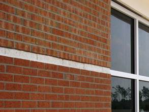
A brick reveal adds interest to a large expanse of facade; in this case, the reveal is aligned with the window muntin
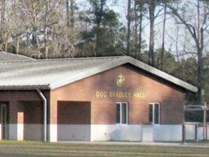
Gable ends are used throughout Camp Johnson, particularly to announce the building's primary entrance
precedents
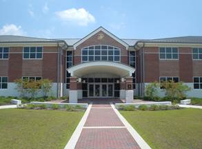
The academic instruction facility, M-79, is the leading precedent for design at Camp Johnson
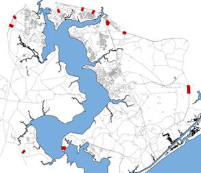
Entry gates, or entry control points, are gateways which functionally serve as check points for access, control, and security, as well as primary locations for informational and directional help. They also establish the initial impression of the Installation, both to visitors and to passers-by. This section applies to these structure directly associated with the entry gate, such as shelters, visitor centers, and pass offices.
Perimeter appearance is important to convey a positive impression of MCB Camp Lejeune and MCAS New River to the city of Jacksonville and the surrounding civilian community. Designs on the perimeter of the Installation such as these should utilize the latest technology for protection and minimize or mitigate the stronghold appearance of barbed wire and no-man zones. Public view planes must also be considered in order to enhance the appearance of the Installations from outside their borders.
Massing
Building massing at Entry Gates shall be based on the Georgian and Colonial Revival styles. Symmetry in building mass, windows, and roof shall be a large determinant of design.
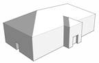
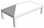
Allowable roof forms are gable-on-hip and hip at slopes between 4:12 and 6:12.
Windows and Entrances
Windows and entrances shall be designed to match the historic Georgian districts of MCB Camp Lejeune. Window dimensions shall fall within a range of 1:1.6 to 1:2 ratio of width to height, as shown in the diagram below. Windows shall have evenly spaced muntins dividing the glazing into 4, 6, or 8 parts to emphasize the historic look.
Window heads and sills shall be detailed to avoid a punched opening affect. This can be accomplished with different types of lintels which blend with the historic character, such as the jack arch or segmental arch. Sills may be precast concrete (preferred) or special brick shapes.
(Left) Example of jack arch using brick or precast concrete; (Right) Example of precast concrete sill
Entrances shall provide some type of weather protection, such as a pocketed door or canopy. Entrances must be formal, clearly identifiable and located toward the most common approach, preferably facing the public way or open space.
Body and Roof Materials
All facades at Entry Gates shall be face brick, modular size. Base foundations may be architectural concrete block, precast concrete, or cast-in-place concrete with a high quality rubbed finish.
Roofing shall be standing seam metal with high standing seams between 12 and 18 inches on center.
Colors entry gates
Description
|
Color
|
|
Facade
|
|
|
Building body
Screen walls
|
red flashed wire cut
standard gray mortar
|
|
Base Foundation
|
white split face
white mortar
|
|
Metal Panel
|
sandstone
BM: OC-48
PANTONE: 400
FED STD: 17875
|
|
Painted Surfaces and Factory Finishes
|
|
Exterior stairs
Utilities/equipment
Appurtenances
|
slate gray
BM: 2133-40
PANTONE: 444
FED STD: 36173
|
|
Gutters/downspouts
Fascia/soffit/frieze
|
bone white
BM: 2140-70
PANTONE: 9041
FED STD: 37875
|
|
Handrails
|
clear anodized aluminum
|
|
Entry accents
Doors
Window/door trim
|
bone white
BM: 2140-70
PANTONE: 9041
FED STD: 37875
|
|
|
clear anodized aluminum
|
|
Roof Cladding
|
|
|
Metal roof
|
medium bronze
BM: 2137-20
PANTONE: 405
FED STD: 33070
|
Details
Entry gates shall reflect the predominant architectural style of the Installation: Georgian and Colonial Revival. Ornament on structures at entry gate districts shall re-inforce this trend. Details commonly associated with these styles include:
· Base foundations
· Molded cornices
· Cupolas
· Decorative fencing
Proportion of the water table line and the height of the cornice detail to the overall building height shall be carefully controlled such that the respective dimensions of these elements are as follows:

The gable end on a gable-on-hip roof shall be equal in height to 1/3 of the overall roof height.
Molded details are apparent on the soffit and fascia as well as the capital of the brick column of the Holcomb Boulevard entry gate.


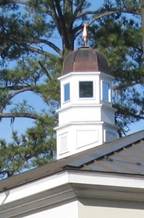
Existing cupola at the Holcomb Boulevard entry gate.
Most cupolas on MCB Camp Lejeune are eight sided with domical roofs and finials such as the ones shown above.
Fencing in Entry Gate districts shall be decorative as well as functional. Break up the visual impact of fences using a black finish on metal work and piers to provide visual interest.
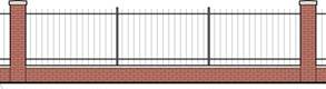
Precedents
The precedent for canopies and gate houses at entry gates is the Holcomb Boulevard entry control point.
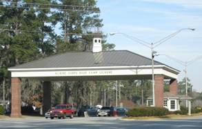
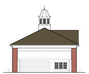
Side elevation of a standard entry control point with guard house beneath.

This district consists of both the Greater Sandy Run training area and the training area across Highway 17, locally known as Verona Loop. This area provides Camp Lejeune with the majority of its maneuver training land. This district is outside the main cantonment area and is not intended for development. However, the few structures and facilities that are built in Greater Sandy Run shall adhere to a basic, consistent set of good design practices and color palette. Camp Devil Dog, situated in the vicinity of Verona Loop, is defined in a separate district within this document.
Massing
Building mass shall be basic and functional.
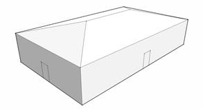
Allowable roof forms are gable and hip at slopes above 2:12 but no greater than 4:12. Eave overhangs shall be extended in order to lessen door and window exposure to the elements.

Windows and Entrances
Windows and entrances shall be designed to meet the facility functional requirements.


Window heads and sills shall be detailed to provide maximum functionality and durability, with deeply recessed frames and properly sloped sills. Sills may be precast concrete (preferred) or special block shapes. Window size and height shall be designed with an emphasis on providing daylight glazing over vision glazing. This may result in high rows of windows along the façade.
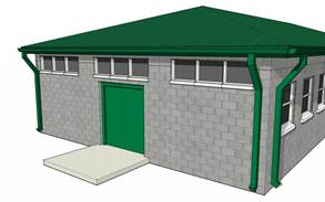
High windows provide daylighting in range facilities which might otherwise have limited or no lighting.
Entrances shall provide some type of weather protection, such as a pocketed door or canopy.
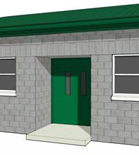
Body and Roof Materials
All facades shall be split face masonry, 8" high by 16" long nominal, or metal panel or a combination of the two. Metal panels shall have a flat profile with panel widths of 36 inches or greater and may consist of 100 percent of the facade.

Roofing shall be either standing seam metal or composition shingle. Metal roof shall have high standing seams between 12 and 18 inches on center.
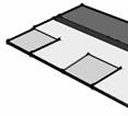
Asphalt shingles shall be laminated architectural shingles with a dimensional appearance.
Colors greater sandy run
Description
|
Color
|
|
Facade
|
|
|
Building body
Screen walls
|
gray split face
standard gray mortar
|
|
Metal Panel
|
sandstone
BM: OC-48
PANTONE: 400
FED STD: 17875
|
|
Painted Surfaces and Factory Finishes
|
|
Exterior stairs
Utilities/equipment
Appurtenances
|
slate gray
BM: 2133-40
PANTONE: 444
FED STD: 36173
|
|
Gutters/downspouts
Fascia/soffit/frieze
|
evergreen
BM: 2040-10
PANTONE: 7484
FED STD: 14109
|
|
Handrails
|
slate gray
BM: 2133-40
PANTONE: 444
FED STD: 36173
|
|
Entry accents
Doors
Door trim
|
evergreen
BM: 2040-10
PANTONE: 7484
FED STD: 14109
|
|
Window trim
|
bone white
BM: 2140-70
PANTONE: 9041
FED STD: 37875
|
|
Roof Cladding
|
|
|
Metal roof
|
evergreen
BM: 2040-10
PANTONE: 7484
FED STD: 14109
|
|
Composition shingle
|
slate gray
|
Details
Minimal details are required in the Greater Sandy Run District and should be limited to creative use of concrete masonry units within the building façade. Soldier courses, such as shown below, are appropriate, as well as other orientations, patterns and bond types.


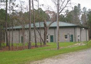
Typical Range Latrine Facility
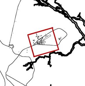
Camp Devil Dog covers approximate 134 acres and consists of austere training facilities primarily used by the School of Infantry. Buildings are generally utilitarian in nature and functional in design with little or no ornament.
Massing
Building mass shall be basic and functional. Roofs to be gable with slopes between 4:12 and 6:12.
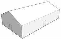
Windows and Entrances

Window heads and sills shall be detailed to provide maximum functionality and durability, with deeply recessed frames and properly sloped sills. Sills may be precast concrete (preferred) or special block shapes. Window size and height shall be designed with an emphasis on providing daylight glazing over vision glazing. This may result in high rows of windows along the façade.
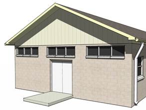
High windows provide daylighting in range facilities which might otherwise have limited or no lighting.
Entrances shall provide some type of weather protection, such as a pocketed door or canopy.
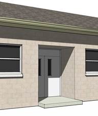
Body and Roof Materials
All facades shall be split face masonry, 8" high by 16" long nominal, or metal panel or a combination of the two. Metal panels shall have a flat profile with panel widths of 36 inches or greater and may consist of 100 percent of the facade.

Roofing shall be either standing seam metal or composition shingle. Metal roof shall have high standing seams between 12 and 18 inches on center.

Asphalt shingles shall be laminated architectural shingles with a dimensional appearance.
Colors common
Description
|
Color
|
|
Facade
|
|
|
Building body
Screen walls
|
cream split face
mortar to match
|
|
|
gray split face
standard gray mortar
|
|
Metal panel
|
almond
BM: OC-32
PANTONE: 9583
FED STD: 27722
|
|
Painted Surfaces and Factory Finishes
|
|
Exterior stairs
Utilities/equipment
Appurtenances
|
slate gray
BM: 2133-40
PANTONE: 444
FED STD: 36173
|
|
Gutters/downspouts
Fascia/soffit/frieze
|
bone white
BM: 2140-70
PANTONE: 9041
FED STD: 37875
|
|
|
evergreen
BM: 2040-10
PANTONE: 7484
FED STD: 14109
|
|
Handrails
|
slate gray
BM: 2133-40
PANTONE: 444
FED STD: 36173
|
|
Entry accents
Doors
|
bone white
BM: 2140-70
PANTONE: 9041
FED STD: 37875
|
|
|
evergreen
BM: 2040-10
PANTONE: 7484
FED STD: 14109
|
|
Window/door trim
|
bone white
BM: 2140-70
PANTONE: 9041
FED STD: 37875
|
|
|
evergreen
BM: 2040-10
PANTONE: 7484
FED STD: 14109
|
|
Roof Cladding
|
|
|
Metal roof
|
almond
BM: OC-32
PANTONE: 9583
FED STD: 27722
|
|
Composition shingle
|
slate gray
|
Details
Eave and rake overhangs shall be extended in order to lessen door and window exposure to the elements.

PRECEDENTS
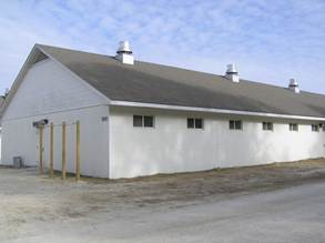
Building DD34 is a good example of a basic and functional facility at Camp Devil Dog.
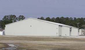
Recently-constructed classroom building at Camp Devil Dog
Certain development on the installation involves third party organizations with its own architectural interests. Therefore this section of the BEAP addresses those areas where the designer, the installation, and the third party must cooperate to meet both the intent of the BEAP and fulfill the organization’s goals.
Department of Defense Education Activity is responsible for the funding, design, and construction of K-12 schools on Camp Lejeune and New River. In the past, DODEA generally works with the Base to comply with the BEAP. New and renovated schools shall comply with the BEAP Common District guidelines as well as other sections of this document as applicable.
Existing DODEA schools on Camp Lejeune are generally constructed with brick facades with modest brick accent details. Roofs are often hip or gable and clad in standing seam metal, although there are several with low slope roofs. School sites are circulation intensive, have large buffers from parking and little landscaping.
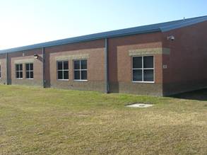
Johnson Primary School can be improved with landscaping. Shading devices such as roof overhangs or louvers are preferred for blocking direct sunlight and enrich the façade.
While the existing schools are of generally good appearance, they should appear welcoming and familiar as opposed to commercial. In addition to the guidelines in the Common District, other elements that can achieve this include:
· Improved landscaping
· Design elements that evoke a more residential character
· Covered transitional spaces between inside and outside
· Soffitted eaves
The Marine Corps Community Services (MCCS) is responsible for the coordination of private vendor facilities. Private vendors are permitted to occupy or construct retail facilities on the Installation. This benefits Marines and civilians by providing convenient and popular services on Base, while also giving the vendor a location with a high amount of traffic. While this is a mutually beneficial relationship, a vendor’s brand colors, materials, and forms sometimes conflict with the standards set forth by the BEAP and the aesthetic goals of Camp Lejeune. Nevertheless, private vendors shall compy with the BEAP.
The commercialization of Special Districts, such as at Hadnot Point and New River, occur along highly visible main gate access roads. It is particularly important that these concentrations of vendors comply with the BEAP's unifying styles, materials and colors. In the case of Hadnot Point, the BEAP defines a Marine Corps Exchange Sub-district, which allows greater flexibility in massing and facade material.
There are many precedents for the adaptation of commercial brands to match local design guidelines as well as contextual surroundings, for example, a substitution of colors and styles such as in the image below. This McDonald's restaurant in Sedona, Arizona uses the historical pueblo style and a teal logo in lieu of the corporate standard design, showing that compliance need not sacrifice brand recognition.
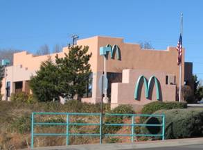
Family housing on MCB Camp Lejeune and MCAS New River is managed by a Public-Private Venture company and is in the process of continual upgrades to the physical appearance of the Installations' housing stock. In general, these upgrades are consistent with the local vernacular and result in a positive contribution to the overall character of the districts, particularly Paradise Point, Tarawa Terrace, and New River.
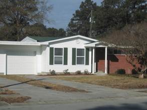
Recently upgraded housing on MCAS New River
New or renovated housing shall continue to be styled after regional vernacular, contemporary interpretations of early American styles, or in a classically based design, depending on the circumstance.
The goal of the BEAP is to establish guidelines to create a safe, productive, and attractive installation and preserve the character of the visual environment. To ensure compliance with the BEAP, an Architectural Review Board will review all projects during design phase, including new construction and major renovation.
This chapter establishes the creation and composition of a group known at the Architectural Review Board. This Board shall administer the procedural guidelines and standards adopted by the Installation under the BEAP. The Architectural Review Board derives its authority from the Base Order.
The Board shall consist of the following:
1. One member from the Installation Development Division
2. One member from the Public Works Division
3. One member from each Activity for which a structure is being designed
4. One Ad hoc member, as needed based on projects under consideration
The Deputy Director, Installations and Environment Department shall serve as non-sitting Chairperson and only rule on decisions when required, such as in the case of a split decision.
The Architectural Review Board shall hold regular monthly meetings on such days and at hours as are set by the Board. In any event, the Board shall meet within 30 days after the submittal of application for a BEAP compliance certificate. If required by the complexity or scope of a project, such time may be extended by the Board. Special meetings may be held at such times as may be fixed by the Review Board or upon the call of the board chairperson. In the event that a contractor requests emergency repairs within a historic district, the Review Board shall consider the application within five business days, or as soon as thereafter as circumstances permit.
The Architectural Review Board shall review matters submitted for its consideration with reference to the goal of achieving coordinated and harmonious development in order to promote the safety, productivity, and beauty of Marine Corps Base Camp Lejeune and Marine Corps Air Station New River. The committee will consider the compatibility of proposed projects with the surrounding environment and such other details as scale, form, materials, color, landscaping, and site appurtenances. Reviews shall be based on their compliance with BEAP design guidelines.
The Architectural Review Board shall issue BEAP compliance certificates, administration of BEAP guidelines, procedural guidelines, and hearing of requests for reconsideration from violations of the BEAP and denials of compliance certificates.
Matters within purview of the Board shall include:
1. New structures, buildings and additions, including site and architecture, regardless of size.
2. Additions or renovations to structures within a historic district, regardless of size or scope.
3. Major site plan changes that involve parking, landscaping, lighting or signs
4. Statues, monuments, memorial structures and other works proposed.
5. New structures, buildings and additions undertaken by private vendors operating on the Installation.
6. Other requests by the Director, Installations and Environment Department
Exceptions:
1. Rehabilitation projects where the work involves restoration of existing materials or repair and replacement with the same materials.
2. Projects as declared exempt by the Director, Installations and Environment Department.
Projects require a two-stage application process (see Dates and Process). Applicants should include one original and 4 copies of the application form, all descriptions, specifications, plans, photographs, and sketches. Provide one set of physical samples. Submittal requirements are the same for each stage of the process.
See Section 6.5 - Application for Certificate of Compliance
· Site plan with proposed building(s) indicated, as well as adjacent streets, on-site parking, stormwater management features, landscaping and proposed plant list, and all site improvements as needed
· Color-rendered front and side elevations drawn at not less than 1/8”=1’-0” scale
· Proposed project exterior signage
· Physical samples of the primary exterior materials, which may include masonry, concrete, siding, paint finishes, and roofing material
· Samples, photographs, and/or brochures of doors, windows, ornamentation, and other exterior materials
· Photos of all adjoining or opposite buildings
Submittal materials may be used by the Board for comparison to adjacent architectural context and will not be returned.
· Site plan with addition(s) shown if a change in the building footprint of the main structure is involved
· Elevations of front and/or sides at not less than 1/8”=1’-0” scale to show intended alterations
· Physical samples of the primary exterior materials, which may include masonry, concrete, siding, paint finishes, and roofing material
· Samples, photographs, and/or brochures of doors, windows, ornamentation, and other exterior materials
· Photos of all adjoining or opposite buildings
Submittal materials may be used by the Board for comparison to the existing architecture and will not be returned.
1. Submit applications and all supporting information to the Director, Installations and Environment Department, MCB Camp Lejeune. Address to the attention of the Architectural Review Board. In case of emergencies, the Board will hear applications no later than five business days after the filing of a complete application. Only complete applications will be considered.
2. The Architectural Review Board will consider a project twice during design: at the Design Development and the Pre-Final Design Submittals. At Design Development or 35% Submittal, the Board will be largely concerned with site, massing, windows, entrances, and materials. At Pre-Final or 100% Submittal, the Board will be concerned with all aspects of site and architecture, and particularly ornamental details and colors. This two-stage process ensures that the design direction is in compliance with the BEAP.
3. The Architectural Review Board will meet to review applications regularly at such time as the Board deems appropriate. Special meetings may be held upon notification by the Chairperson of the Board to all members that an emergency application has been filed. At this meeting, the application will be considered.
4. Upon receipt of an application, the Architectural Review Board may permit modifications of an original proposal if such modifications are clearly indicated by the applicant and recorded by the Board.
5. The Architectural Review Board will visit the project site to verify it’s architectural and environmental context and judge the appropriateness of the design's form, materials, and colors.
6. Architectural Review Board meetings are not public and there is no requirement for applicants to be present. If applicants wish to meet with Board members, they may request to do so in writing to the Board Chairperson. Applicants will be informed of the Board decision within five business days after the meeting has occurred.
The Architectural Review Board shall deny the application for a certificate of compliance if it finds:
· That the action proposed would adversely affect or be incompatible with the character of the district in which it is to be taken
· That the action proposed would not be consistent with the character of a historic district
· That the proposed action would not be consistent with the Base Exterior Architectural Plan adopted by the Installation
Where certification is denied, the Architectural Review Board shall record its reasons for denial. There shall be no re-considerations until the applicant properly addresses the reasons for denial.

return to:
Director
Installations and Environment Department
Building 12
MCB Camp Lejeune, NC 28542
APPLICATION INFORMATION
Project Number
Project Name
Contract Number
Project Location/Street
Brief Project Description
Type of Review
p Discussion Only p 35% p 100%
APPLICANT INFORMATION
Applicant Name
Applicant Address
Phone/Email
APPLICATION CHECKLIST
Scope of Project:
p New Construction
p Exterior Renovation/Alteration
p Addition
p Historic District/Building
p Signage
p Landscaping
p Re-roofing
Submittal Requirements:
p Project narrative describing context and BEAP compliance for site/building (2 pages)
p Site plan, includes the following:
p Adjacent streets
p Parking
p Stormwater management features
p Landscaping
p Plant list
p Front elevation color rendering 1/8" scale
p Side elevations color rendering 1/8" scale
p Exterior signage
p Samples of primary exterior materials
p Samples of doors, windows, ornament
p Color photographs of adjoining or adjacent buildings
Signature of Applicant Date
For This Review Only
p in compliance
p Not in compliance
p certificate granted
Remarks
Whom to contact for more information:
Name
Phone/Email
Field work for the BEAP Study consisted of several phases:
· Initial kickoff meeting included all stakeholders and established the scope of the study and the districts to be included
· A Windshield Survey reviewed the significant structures on the Installations and prioritized future survey work; a representative sample of buildings and landscapes were identified and provided to the Installations
· An in-depth Special District Survey of each district studied individual buildings in regards to style, form, context, and site; this survey covered 300 buildings
· Final site visit and individual interviews provided details on planning, operations, and maintenance
The scope of work for the survey closely followed the Naval Facilities Engineer Command Installation Appearance Guide, found at https://portal.navfac.navy.mil/portal/page/portal/iag
Comprehensive data collection gathered information on the Installations' history, historic structures, artifacts, community and culture. The primary sources of information for data collection included:
· Real Property Inventory
· Internet Naval Facilities Assets Data Store (iNFADS)
· Facility Surveys
· Design Criteria
· Development Plans
· Building Plans
· Zoning Maps
· Base Orders
· Stakeholder Interviews
· GIS Data
The land area of interest covered by the scope of work included the coastal plains region of North Carolina, Onslow County, and the City of Jacksonville. The specific land area surveyed included:
· MCB Camp Lejeune cantonment area, including:
− Onslow Beach
− Courthouse Bay
− Stone Bay
· MCAS New River cantonment area
· Sandy Run Training Area
· Camp Devil Dog Training Area
· Camp Geiger
· Camp Johnson
· Tarawa Terrace Housing Area
· Port Facilities at Morehead City
· Outlying Landing Field at Oak Grove
The Windshield Survey identified significant buildings which contributed to the character of the Installation. The team developed a Survey Matrix which contained the following items to describe each building: name, number, function, date constructed, district, materials, colors, form, style, scale, historic nature, and relationship to context. A total of 313 buildings were addressed in the matrix, located in 19 Special Districts or named areas. The iNFADS data base and GIS Data were instrumental in developing the matrix.
The in-depth Special District Survey was conducted at MCB Camp Lejeune and MCAS New River over a period of one week with several follow-up visits. The Survey Matrix was used to guide this effort, where the majority of the physical information, including photographs, was collected.
The team conducted interviews with stakeholders during the Special District Survey, follow-up visits and over the phone. These individuals included planners, property managers, maintenance personnel, and other administrative officers of the Base and Special Districts. Specifically from:
· Installation Development
· Environmental Management
· Family Housing
· Marine Corps Community Services
· MCB Camp Lejeune Public Works
· MCAS New River Public Works
· Base Operations
· DODEA Schools
· Onslow Beach General Management
· School of Infantry -- East
The field work concluded with a presentation to stakeholders on the team's findings and recommendations on how to proceed with the BEAP study.
Common Operating Levels are a method of addressing what and where appearance items are prioritized. COLs establishes a hierarchy of treatment zones and related allocation of resources, including funding for planned maintenance (based on life-cycle costs) at the time of planning and design for the project.
For the purpose of the COLs, the Installation is defined by functional zones. The zones in this study include:
· Waterfront: Facilities which provides the physical interface between ship and shore side functions.
· Airfield: Facilities associated with activities related to aircraft and their maintenance and support functions
· Industrial: Facilities associated with all manner of activities not directly related to waterfronts or airfields
· Training: Facilities where Marines and other personnel receive training and instruction in their career field
· Administrative: Facilities which contain offices, conference rooms, and command settings
· Personnel Support/Unaccompanied Quarters: Facilities related to support of the Marine and their family members
COLs are developed by overlaying these functional districts with the circulation on the Installation, resulting in a combined overlay. Circulation is established using the following categories:
· Entry Gate: Installation entry gates
· Primary Roads: Main thoroughfares, usually with 2 to 4 lanes and median
· Secondary Roads: Secondary or collector roads usually with 2 lanes
· Tertiary Roads: Roads used to access local buildings and parking lots on the Installation
|
|
Circulation
|
|
Functional Zone
|
Entry Gate
|
Primary
|
Secondary
|
Tertiary
|
|
Waterfront
|
I
|
II
|
II
|
III
|
|
Airfield
|
I
|
II
|
II
|
III
|
|
Industrial
|
I
|
II
|
III
|
IV
|
|
Training
|
I
|
I
|
II
|
III
|
|
Administrative
|
I
|
I
|
II
|
III
|
|
Personnel Support
|
I
|
I
|
II
|
III
|
|
Family Housing
|
I
|
I
|
II
|
III
|
|
Undeveloped
|
I
|
II
|
III
|
IV
|
Legend:
|
I
|
Highest priority; greatest public exposure and sensitivity to image and local context
|
|
II
|
Lesser priority than I, but significant public exposure and sensitivity
|
|
III
|
Lesser priority than II; limited public exposure, but possible sensitivity
|
|
IV
|
Lowest priority; limited public exposure, least sensitivity; but may be redeveloped
|
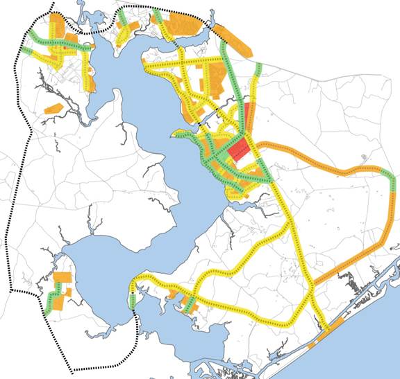
MCB Camp Lejeune and MCAS New River COLs

This map is an approximation of a 500 mile radius centered on Camp Lejeune. Materials used in projects which are extracted and manufactured within this region may qualify for LEED® points. Refer to the LEED® guidelines and other resources located on the Whole Building Design Guide (WBDG) website (www.wbdg.org/design/sustainable.php).

|
|
Height
|
Spread
|
Growth Rate
|
Winter Form
|
Foliage
|
Bark
|
Flower / Fruit
|
Fall Color
|
Wet Soil Tolerant
|
Poor Soil Tolerant
|
Drought Tolerant
|
Pollution Tolerant.
|
Salt Tolerant
|
Full Sun Tolerant
|
Shade Tolerant
|
Lawn
|
Street Tree / Parking Area
|
Screen / Wind Break
|
Accent / Specimen
|
Mass Planting
|
|
Large Deciduous Trees
|
|
Acer rubrum
Red Maple
|
40-60'
|
35-50'
|
M
|
|
|
|
|
•
|
|
|
|
|
|
•
|
|
•
|
•
|
|
•
|
|
|
Liriodendron tulipifera
Tulip tree
|
70-90’
|
35-50’
|
F
|
|
•
|
|
•
|
•
|
|
|
|
|
|
•
|
|
•
|
|
|
•
|
•
|
|
Liquidambar styraciflua
Sweetgum
|
60-75’
|
40-50’
|
M
|
|
•
|
|
|
•
|
|
|
|
|
|
•
|
|
•
|
|
|
•
|
|
|
Quercus cocinea
Scarlet Oak
|
70-75’
|
40-50
|
F
|
|
|
|
|
•
|
|
•
|
•
|
|
|
•
|
|
•
|
•
|
|
|
|
|
Quercus hemisphaerica
Laurel Oak
|
40-60’
|
30-40’
|
F
|
|
|
|
|
|
•
|
•
|
•
|
|
•
|
•
|
|
•
|
•
|
|
|
|
|
Quercus phellos
Willow Oak
|
40-60'
|
30-40'
|
F
|
|
|
|
|
•
|
•
|
|
|
•
|
|
•
|
|
•
|
•
|
|
|
|
|
Quercus rubra
Red Oak
|
60-75'
|
40-50'
|
F
|
|
|
|
|
•
|
|
|
|
•
|
•
|
•
|
|
•
|
•
|
|
|
•
|
|
Sophora japonica
Japanese Pagoda Tree
|
50-75'
|
50-75'
|
F
|
|
•
|
|
•
|
|
|
•
|
•
|
•
|
|
|
|
•
|
|
|
|
•
|
|
Taxodium distichum
Bald Cypress
|
50-70'
|
20-30'
|
M
|
|
•
|
|
|
|
•
|
•
|
•
|
•
|
|
|
|
•
|
|
|
•
|
|
|
Tilia tomentosa
Silver Linden
|
50-70'
|
25-50'
|
M
|
|
•
|
•
|
|
|
|
|
•
|
|
|
|
|
•
|
•
|
|
•
|
|
|
Zelkova serrata
Japanese Zelkova
|
50-80'
|
50-80'
|
F
|
•
|
|
•
|
|
•
|
|
|
•
|
•
|
|
|
|
•
|
•
|
|
|
|
|
|
Height
|
Spread
|
Growth Rate
|
Winter Form
|
Foliage
|
Bark
|
Flower / Fruit
|
Fall Color
|
Wet Soil Tolerant
|
Poor Soil Tolerant
|
Drought Tolerant
|
Pollution Tolerant.
|
Salt Tolerant
|
Full Sun Tolerant
|
Shade Tolerant
|
Lawn
|
Street Tree / Parking Area
|
Screen / Wind Break
|
Accent / Specimen
|
Mass Planting
|
|
Medium Deciduous Trees
|
|
Carpinus betulus 'Fastigata'
Upright European Hornbeam
|
30-40'
|
20-30'
|
S
|
|
|
|
|
|
|
|
|
|
|
•
|
|
|
•
|
•
|
|
•
|
|
Gleditsia triacanthos var. inermis Shade- master'
Thornless Honeylocust
|
30-70'
|
30-70'
|
F
|
|
•
|
|
|
•
|
|
|
•
|
•
|
•
|
•
|
|
•
|
•
|
|
|
|
|
Oxydendrum arboreum
Sourwood
|
25-40'
|
20'
|
S
|
|
|
|
•
|
•
|
|
|
|
|
|
•
|
•
|
•
|
|
|
•
|
|
|
Pyrus calleryana 'Red Spire'
Red Spire Callery Pear
|
30-50'
|
20-35'
|
M
|
|
|
|
•
|
•
|
|
|
•
|
•
|
|
•
|
|
•
|
•
|
|
•
|
|
|
|
Height
|
Spread
|
Growth Rate
|
Winter Form
|
Foliage
|
Bark
|
Flower / Fruit
|
Fall Color
|
Wet Soil Tolerant
|
Poor Soil Tolerant
|
Drought Tolerant
|
Pollution Tolerant.
|
Salt Tolerant
|
Full Sun Tolerant
|
Shade Tolerant
|
Lawn
|
Street Tree / Parking Area
|
Screen / Wind Break
|
Accent / Specimen
|
Mass Planting
|
|
Small Deciduous Trees
|
|
Acer ginnala
Amur Maple
|
15-18'
|
15-25'
|
S
|
|
|
|
|
•
|
|
|
|
|
|
•
|
•
|
|
|
•
|
•
|
•
|
|
Cercis canadensis
Eastern Redbud
|
20-30'
|
20-35'
|
M
|
|
•
|
|
•
|
|
|
|
|
|
|
•
|
•
|
|
|
|
•
|
•
|
|
Cornus kousa
Kousa Dogwood
|
20-30'
|
20-30'
|
S
|
•
|
|
•
|
•
|
|
|
|
|
|
|
•
|
|
|
|
•
|
•
|
|
|
Cornus x Rutgers
Rutgers Hybrid Dogwoods
|
15-20'
|
20-30'
|
M
|
•
|
|
|
•
|
•
|
|
|
|
|
|
•
|
|
|
|
|
•
|
•
|
|
Lagerstroemia x. indica
Crepe Myrtle cultivars
|
10-20'
|
10-15'
|
F
|
|
|
•
|
•
|
|
•
|
•
|
|
•
|
|
•
|
|
|
|
|
•
|
•
|
|
Magnolia stellata
Star Magnolia
|
15-20'
|
10-15'
|
S
|
|
|
|
•
|
|
|
|
|
|
|
|
|
|
|
|
•
|
|
|
Malus x
Flowering Crabapple varieties
|
10-30'
|
20-30'
|
M
|
•
|
•
|
|
•
|
•
|
|
•
|
|
|
|
•
|
|
|
|
|
•
|
•
|
|
|
Height
|
Spread
|
Growth Rate
|
Winter Form
|
Foliage
|
Bark
|
Flower / Fruit
|
Fall Color
|
Wet Soil Tolerant
|
Poor Soil Tolerant
|
Drought Tolerant
|
Pollution Tolerant.
|
Salt Tolerant
|
Full Sun Tolerant
|
Shade Tolerant
|
Lawn
|
Street Tree / Parking Area
|
Screen / Wind Break
|
Accent / Specimen
|
Mass Planting
|
|
Evergreen Trees
|
|
Cedrus deodara
Deodar Cedar
|
40-70'
|
40-70'
|
M
|
•
|
•
|
|
|
|
|
|
•
|
|
|
•
|
|
•
|
|
•
|
•
|
|
|
x Cupressocyparis leylandii
Leyland Cypress
|
60-70'
|
12-20'
|
F
|
•
|
•
|
|
|
|
|
|
|
|
|
•
|
•
|
|
|
•
|
•
|
•
|
|
Ilex x attenuata 'Fosteri'
Foster's Holly
|
15-25'
|
12-15'
|
S
|
•
|
•
|
|
•
|
|
|
|
|
|
|
•
|
•
|
|
|
•
|
•
|
•
|
|
Ilex x 'Nellie R Stevens'
Nellie Stevens Holly
|
15-25'
|
10-15'
|
F
|
•
|
•
|
|
•
|
|
|
|
|
|
|
|
•
|
•
|
|
•
|
•
|
•
|
|
Ilex opaca
American Holly
|
40-50'
|
18-40'
|
M
|
•
|
•
|
|
•
|
|
|
|
|
•
|
|
•
|
|
•
|
|
•
|
|
•
|
|
Quercus virginiana
Live Oak
|
40-80’
|
60-100’
|
S
|
|
|
|
|
|
•
|
•
|
•
|
•
|
•
|
•
|
|
•
|
•
|
|
•
|
|
|
Magnolia grandiflora
Southern Magnolia
|
30-50'
|
30-40'
|
M
|
•
|
•
|
|
•
|
|
|
|
|
•
|
|
•
|
•
|
•
|
|
•
|
•
|
|
|
Pinus strobus
White Pine
|
50-80'
|
20-25'
|
F
|
•
|
•
|
|
|
|
|
•
|
•
|
|
|
•
|
|
|
|
•
|
|
•
|
|
Pinus nigra
Austrian Pine
|
50-60'
|
20-40'
|
M
|
•
|
•
|
•
|
|
|
|
•
|
•
|
•
|
•
|
|
|
|
|
•
|
•
|
•
|
|
|
Height
|
Spread
|
Growth Rate
|
Winter Form
|
Foliage
|
Bark
|
Flower / Fruit
|
Fall Color
|
Wet Soil Tolerant
|
Poor Soil Tolerant
|
Drought Tolerant
|
Pollution Tolerant.
|
Salt Tolerant
|
Full Sun Tolerant
|
Shade Tolerant
|
Lawn
|
Street Tree / Parking Area
|
Screen / Wind Break
|
Accent / Specimen
|
Mass Planting
|
|
Deciduous Shrubs
|
|
Amelanchier arboria
Downy Serviceberry
|
15-25'
|
varies
|
M
|
|
•
|
•
|
•
|
•
|
|
|
|
•
|
•
|
|
|
|
|
|
•
|
|
Aronia arbutifolioa 'Brilliantissma'
Red Chokeberry
|
6-10'
|
3-5'
|
S
|
|
|
•
|
•
|
•
|
•
|
|
|
•
|
•
|
|
|
|
|
|
•
|
|
Clethra alnifolia
Summer Sweet Cultivars
|
3-8'
|
4-6'
|
S
|
|
|
•
|
|
•
|
|
|
|
•
|
•
|
•
|
|
|
|
|
•
|
|
Forsythia x intermedia Forsythia cultivars
|
10'
|
10'
|
F
|
|
|
|
•
|
|
|
|
|
•
|
|
•
|
|
|
|
|
•
|
|
Myrica pennsylvanica
Northern Barberry
|
5-12'
|
5-12'
|
M
|
|
|
•
|
|
|
•
|
|
|
•
|
•
|
•
|
|
|
|
|
•
|
|
Rhododendron calendulaceum
Flame Azalea
|
4-8'
|
4-15'
|
S
|
|
|
•
|
|
|
|
|
|
|
|
|
|
|
•
|
|
|
|
Viburnum plicatum var. tomentosum 'Shasta'
Marie's Doublefile
Viburnum
|
6'
|
10-12'
|
M
|
•
|
|
•
|
•
|
|
|
|
|
|
|
|
•
|
•
|
•
|
|
|
|
Height
|
Spread
|
Growth Rate
|
Winter Form
|
Foliage
|
Bark
|
Flower / Fruit
|
Fall Color
|
Wet Soil Tolerant
|
Poor Soil Tolerant
|
Drought Tolerant
|
Pollution Tolerant.
|
Salt Tolerant
|
Full Sun Tolerant
|
Shade Tolerant
|
Lawn
|
Street Tree / Parking Area
|
Screen / Wind Break
|
Accent / Specimen
|
Mass Planting
|
|
Evergreen Shrubs
|
|
Ilex cornuta
Dwarf Burford Holly
|
5-8'
|
5-10'
|
S
|
|
•
|
|
•
|
|
|
|
|
|
|
|
•
|
|
|
•
|
•
|
•
|
|
Ilex crenata
Japanese Holly
|
3-5'
|
5'
|
S
|
|
•
|
|
|
|
|
|
|
•
|
|
|
•
|
|
|
•
|
|
|
|
Juniperus horizontalis 'Plumosa'
Andorra Juniper
|
2-3'
|
10'
|
S
|
•
|
•
|
|
|
|
|
•
|
•
|
|
|
•
|
|
|
|
•
|
|
|
|
Morella cerifera
Waxmyrtle
|
10-15'
|
5-8'
|
F
|
|
•
|
|
•
|
|
•
|
•
|
|
|
•
|
•
|
•
|
|
|
•
|
|
•
|
|
Pieris japonica
Japanese Pieris
|
9-12'
|
6-8'
|
S
|
|
•
|
|
•
|
|
|
|
|
|
•
|
•
|
•
|
|
|
•
|
|
|
|
Prunus laurocerasus `Schipkaensis'
Schipka Cherry Laurel
|
4-5'
|
8-10'
|
M
|
|
•
|
|
•
|
|
|
|
|
|
|
•
|
•
|
|
|
•
|
|
|
|
Rhodoendron catawbiense
Catawba Rhododendron
|
6-10'
|
5-8'
|
|
|
|
|
•
|
|
|
|
|
|
|
•
|
|
|
|
•
|
|
|
|
Rhododendron obtusum
Kurume Azalea
|
4-6'
|
4-6'
|
S
|
|
•
|
|
•
|
|
|
|
|
|
|
•
|
|
|
|
•
|
|
•
|
|
Taxus x media
‘Densiformis’, ‘Repanda’, ‘Ever-Low’
Dense Spreading Yew Cultivarscultivarscultivars
|
varies
|
varies
|
S
|
|
•
|
|
•
|
|
|
|
|
|
•
|
|
|
|
|
•
|
|
|
|
Taxus x media "Hicksii"
Upright Yew
|
15-20'
|
3-5'
|
|
|
|
|
•
|
|
|
|
|
|
|
•
|
•
|
|
|
•
|
•
|
|
|
Height
|
Spread
|
Growth Rate
|
Winter Form
|
Foliage
|
Bark
|
Flower / Fruit
|
Fall Color
|
Wet Soil Tolerant
|
Poor Soil Tolerant
|
Drought Tolerant
|
Pollution Tolerant.
|
Salt Tolerant
|
Full Sun Tolerant
|
Shade Tolerant
|
Lawn
|
Street Tree / Parking Area
|
Screen / Wind Break
|
Accent / Specimen
|
Mass Planting
|
|
Groundcovers
|
|
Euonymous fortunei 'Coloratus'
Wintercreeper
|
4-6"
|
-
|
F
|
|
•
|
|
|
|
|
•
|
|
|
|
•
|
•
|
|
|
|
•
|
•
|
|
Hedera helix
English Ivy
|
4-6"
|
-
|
F
|
|
4-6"
|
|
|
|
|
•
|
•
|
•
|
|
|
|
|
|
|
|
•
|
|
Juniperus horizontallis
Spreading juniper cultivars
|
12"
|
4-6'
|
S
|
•
|
•
|
|
|
|
|
•
|
•
|
•
|
•
|
•
|
|
|
|
|
|
•
|
|
Liriope spicata
Little blue Lily-turf
|
8-18"
|
-
|
M
|
|
•
|
|
•
|
|
|
|
|
|
|
|
•
|
|
|
|
•
|
•
|
|
Pachysandra terminalis
Japanese spurge
|
6-12"
|
-
|
M
|
|
•
|
|
•
|
|
|
|
|
|
|
|
•
|
|
|
|
|
|
|
Vinca minor
Perwinkle
|
3-6"
|
-
|
M
|
|
•
|
|
•
|
|
|
•
|
|
|
|
|
•
|
|
|
|
|
•
|
‘Hatteras’ American Beach Grass
Ammophila breviligulata ‘Hatteras’
Sea Oats
Uniola paniculata
Bitter panicum
Panicum amarum
Yaupon Holly
Ilex vomitoria
Wax myrtle
Morella cerifera
More extensive dune restoration plant recommendations and details on planting dunes may be obtained from the North Carolina Cooperative Extension http://www.ces.ncsu.edu/.
Sample boards are included with this document to provide designers with accurate characteristics of materials and colors indicated in the guidelines. The images provided in the Special Districts section are intended for reference only and may not be an accurate color, depending on computer monitors or printers. Therefore, matching materials and textures should be done with the physical samples only. The following districts are represented on a board:
· Hadnot Point
· Hospital Point
· French Creek
· Cogdels Creek
· Wallace Creek
· Courthouse Bay
· Paradise Point
· Onslow Beach
· Camp Geiger
· Marine Corps Air Station New River
· Stone Bay
· Camp Johnson
· Entry Gates

Warning: Boards only provide a sample of the colors and materials listed in the Special District sections and do not indicate which colors are appropriate to use in which architectural elements. Therefore the written sections of the BEAP and the boards should be used together to understand the guideline.
To best assist the designer in selecting the desired colors and materials, the following list of material manufacturers is provided. This list is not an endorsement, recommendation, or suggestion of manufacturers or suppliers, but simply identifies where and from whom the samples originated.
|
Color or Material
|
Manufacturer Supplier
|
Name, Number
|
|
Brick
|
|
|
|
red flashed smooth
|
Triangle Brick
Riverside Brick & Supply
|
Flashed Common
|
|
red flashed wire cut
|
Triangle Brick
Riverside Brick & Supply
|
Flashed Wirecut
|
|

blended sand faced
|
Hanson Brick
Oldcastle Adams Products
|
Brentwood
|
|
blended flashed wire cut
|
Belden Brick
Custom Brick Company
|
Tudor Blend
|
|
Concrete masonry
|
|
|
|
white split face
|
Trenwyth
Riverside Brick & Supply
|
Ramapo White
|
|
cream matte face
|
New Holland Concrete
Allied Concrete Company
|
Cream
NO706
|
|
grey split face
|
Trenwyth
Riverside Brick & Supply
|
Williams-burg Grey
|
|
Prefinished metal
|
|
|
|
slate gray
|
PAC-CLAD
Moisture Protection Products
|
Slate Grey
|
|
slate gray
|
Berridge Manufacturing Company
|
Zinc Grey
|
|
sandstone
|
PAC-CLAD
Moisture Protection Products
|
Sandstone
|
|
clear anodized aluminum
|
Kawneer North America
|
Clear
|
|
bone white
|
PAC-CLAD
Moisture Protection Products
|
Bone White
|
|
medium bronze
|
Kawneer North America
|
Medium Bronze
|
|
taupe
|
Berridge Manufacturing Company
|
Buckskin
|
|
evergreen
|
PAC-CLAD
Moisture Protection Products
|
Evergreen
|
|
tan
|
PAC-CLAD
Moisture Protection Products
|
Sierra Tan
|
|

silver
|
IMETCO
Tucker, GA
|
Platinum Silver
|
|
Sloped roof
|
|
|
|

weathered wood
|
CertainTeed Saint-Gobain
|
Weathered Wood
|
|

cedar
|
cedar shingle
|
|
|

slate gray
|
CertainTeed Saint-Gobain
|
Colonial Slate
|
|
Low slope roof
|
|
|
|
white
|
roof cap sheet
|
|
|
Siding
|
|
|
|

tan wood grain
|
CertainTeed Saint-Gobain
|
Antique White
|
|

grey wood grain
|
CertainTeed Saint-Gobain
|
Heather
|

 beap pamphlet
This pamphlet describes the basic appearance standards for minor landscaping, grounds maintenance, building improvements, and painting projects undertaken by Tenant Organizations on MCB Camp Lejeune and MCAS New River.
Plantings provide one of the most effective means of unifying an Organization's area and the Base. Plant like-species trees in rows or clusters of three to five along walks and paths to maximize effectiveness. Small trees with low maintenance, groundcover plants (under 6” height) or turf are suitable within 33' of buildings.
|
Ground Cover
|
Remarks
|
|
Turf
|
|
|
Little Blue Liriope
|
part shade
|
|
English Ivy
|
|
|
Vinca
|
shade
|
|
Trees
|
|
|
Red Maple
|
|
|
Oak: Scarlet, Willow, Live, Laurel, Pin
|
|
|
Tulip Poplar
|
|
|
Sweetgum
|
|
|
Crepe myrtle
|
|
|
Redbud
|
part shade
|
|
Magnolia: Sweetbay, Star
|
|
|
Pine: Japanese Black, Loblolly
American Holly
|
|
Any modification to the exterior of a building affects its architectural character; minor changes, when dispersed across a number of buildings, can impact the overall appearance of an area. Therefore modifications must be done carefully and consistently within the approved architectural style.
The predominant styles found on MCB Camp Lejeune are early American designs. They are characterized by a formal arrangement of classical details based on a symmetrical front elevation. Building elements such as windows and doors are trimmed and roof edge details are molded, often with wood or materials with a wood appearance.
There are several historic areas on MCB Camp Lejeune. No modifications may be made within these areas without special approval from the Base.
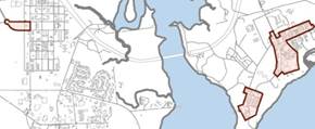
Historic areas in Camp Geiger and Camp Johnson

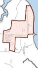
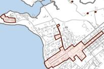
Historic areas in Rifle Range, Hadnot Point, and Courthouse Bay (inset)
Modifications always require a work request before executing, but the following requires prior special approval from the Base prior to undertaking:
|
Description
|
Remarks
|
|
Athletic pits
|
Athletic pits constructed through the Martial Arts Program must be approved through Installation Development. Units which construct athletic pits will be required to maintain them through unit resources.
|
|
Pull up/dip bars
|
Public Works is the proponent for design of pull up/dip bars; all such work must contact Public Works prior to construction
|
|
Memorials
|
Unit insignia on memorials must obtain approval from Installation Development. Units which construct memorials will be required to maintain them through unit resources.
|
|
Flagpoles
|
The National Flag is authorized on the basis of one per Organizational Flag. Refer to Marine Corps Order P10520.3B for a list of authorized organizations.
|
|
Gazebos
|
Gazebo construction must obtain a site approval and undergo a design review from Installation Development.
|
While the Base strongly encourages Organizations to take advantage of the Self-Help program, the uniformity of Base appearance and regular maintenance must be considered. Therefore the Base restricts the following site and building modifications:
|
Description
|
Image
|
Alternative
|
|
Rope and wood post fencing
|
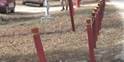
|
None
|
|
Unauthorized parking signs
|

|
Base Order permits marking paved surfaces
|
|
Landscape timbers
|

|
Landscape paver blocks
|
|
Exposed cable television cabling
|
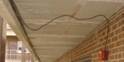
|
None
|
|
Roof-mounted commercial and tactical antennas
|

|
Mount to side of structure, requires approval from Tower Working Group
|
|
Painted exterior stairways
|

|
None
|
|
Car ports or other covered storage
|

|
Work request for gazebo or picnic shelter
|
· Base Exterior Architectural Plan, available from Installation Development
· Guidelines for Historical Buildings Management, available from Environmental Management
Public Works, Self Help451-2970
Installation Development451-1833
Environmental Management451-5003
ACRONYMS AND ABBREVIATIONS
ADAAG Americans with Disability Act Accessibility Guide
ADA Americans with Disabilities Act
ATFP Antiterrorism/Force Protection
BEAP Base Exterior Architecture Plan
BEQ Bachelor Enlisted Quarters
CMU Concrete Masonry Unit
COLs Common Operational Levels
DoD Department of Defense
DoN Department of the Navy
FEC Facilities Engineering Command
FED-STD Federal Standard 595B Colors
HQ Headquarters
IAG Installation Appearance Guide
IAP Installation Appearance Plan
IES Illuminating Engineers Society
LEED Leadership in Energy and Environmental Design
LID Low Impact Development
MCAS Marine Corps Air Station
MCB Marine Corps Base
MCON Military Construction Navy Project
MILCON Military Construction Project
NRHP National Register of Historic Places
OLF Outlying Landing Field
POV Privately Owned Vehicle
PPV Public/Private Venture
PWD Public Works Division
SHPO State Historic Preservation Office
UFAS Uniform Federal Accessibility Standards
UFC United Facilities Criteria
USGBC United States Green Building Council
Blumenson, John J.-G. Identifying American Architecture. Nashville, American Association for State and Local History, 1985.
Ching, Francis D. K. Architecture: Form, Space, & Order. New York, New York, Van Nostrand Keinhold, 1979.
The Louis Berger Group. Guidelines for Historic Buildings Management, Marine Corps Base, Camp Lejeune, Onslow County, North Carolina. August 2008.
Mullins, Lisa C, editor. Colonial Architecture of the Mid-Atlantic. Pittstown, New Jersey, The National Historical Society, 1987.
Mullins, Lisa C, editor. Architectural Treasures of Early America. Harrisburg, Pennsylvania, The National Historical Society, 1987.
Naval Facilities Engineering Commmand Asset Management Business Line. “Navy Installation Appearance Guide.” Navy Facility Engineering Command. https://portal.navfac.navy.mil/portal/page/portal/bd/iag
The Onyx Group. Base Exterior Architectural Plan Camp Lejeune. March 1997.